
Related Manuals for Kenwood FC-757


Summary of Contents for Kenwood FC-757
- Page 1 UNIVERSAL COUNTER FC-757 INSTRUCTION MANUAL KENWOOD CORPORATION ©PRINTED IN * N B50-7726-00 ( N ) 06106...
-
Page 2: Table Of Contents
CONTENTS G E N E R A L ..S P E C I F I C A T I O N S 3. " P R E C A U T I O N S F O R U S E P A N E L E X P L A N A T I O N 4 - 1 . -
Page 3: G E N E R A L
G E N E R A L The FC-757 is a universal counter. It can be used to — T i m e measurement function measure frequencies (175MHz M a x . ) , period, frequency The time measurement function... - Page 4 S P E C I F I C A T O N S x 1 , x 1 0 , x 1 0 0 , X1000 M a g n i f i c a t i o n [Frequency Measurement (Channel A ) ] ( G a t e time) [Frequency Ratio Measurement ( A / B ) ]...
- Page 5 Single-shot pulse W a i t by reset A t t e n u a t i o n x 1 ( 1 / 1 ) , x 1 0 ( 1 x 1 0 ) processing L o w pass f i l t e r 10kHz, - 3 d B [Event input Total Measurement ( A ) ]...
- Page 6 0.01s, 0.1s, 1.0s, 10s Counting time 3 x 1 0 - / 0 to 40 °C S t a b i l i z a t i o n 5 x 1 0 ' / m o n t h ( G a t e time) (Tenperature f a c t o r , aging rate)
-
Page 7: Precautions For Use
PRECAUTIONS FOR USE T u r n off the product and then connect it w i t h T h i s counter can s t a r t its operation a t the A C w a l l outlet by using the accessory power moment when power is applied. -
Page 8: Panel E X P L A N A T I O N
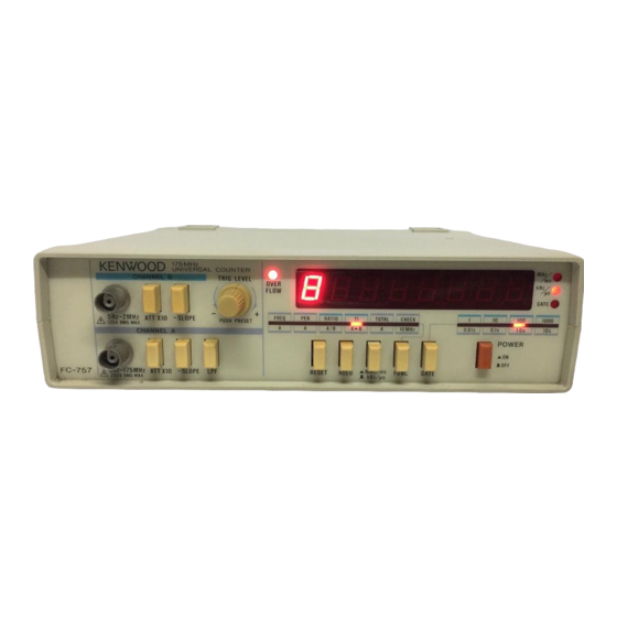
PANEL E X P L A N A T I O N interval is being measured. T h i s L E D indicator 4 - 1 F r o n t panel becomes inactive when the frequency r a t i o meas- ®... - Page 9 Figure 1. F r o n t panel...
- Page 10 attenuatjon. © Display ( L E D ) Note t h a t t h i s s w i t c h can work together w i t h The display consists of eight-digit L E D s channel B only but does not affect channel A . indicating a l l the current measurement value.
- Page 11 terminated w i t h a resistor of 1.2 megaohm. © L P F S w i t c h m a x i m u m input voltage is 2 5 0 V r m s . L P F s w i t c h is used to enable the low pass ©...
- Page 12 Event t o t a l counter ( T O T A L / A ) mode : © R E S E T S w i t c h If this s w i t c h is pressed ) , the current R E S E T...
- Page 13 • T h i s switch is helpless in the frequency r a t i o range : measurement mode and event t o t a l count meas- 5Hz to 10MHz urement mode, Measurement s e n s i t i v i t y : ®...
- Page 14 e. ' T O T A L / A (event input t o t a l count) mode R A T I O A / B (frequency r a t i o ) mode The T O T A L / A mode is an operational mode The R A T I O A / B mode is an operational mode...
-
Page 15: Rear Panel
4 - 2 Rear panel ( T O T A L / A ) mode. © T O T A L I Z E I N P U T S T A R T / S T O P Input juck The G A T E L E D is also provided to... - Page 16 F o r the 220V or 240V-power requirement, use If this s w i t c h is set to the E X T . side, the the 0.125A/250V slow-blow type fuse. universal counter can be connected w i t h an When you replace the current fuse, refer external 1 0 - M H z time base clock generator v i a section 7-1 'Maintenance'...
- Page 17 Figure 2. Rear panel...
-
Page 18: Case Surface
4 - 3 Case surface The opening is normally covered w i t h a rubber ® There is an opening on the case surface. T h i s cap. If the T C X O needs to be fine adjusted, opening is provided for fine adjustment of please contact your dealer. -
Page 19: Operating Procedures
OPERATING PROCEDURES E v e r y time when you s t a r t using the FC-757 M u l t i - Select the F R E Q / A mode by using F U N C Functional universal counter, look a t the rear panel switch @ . - Page 20 If R E S E T s w i t c h © is pressed during frequency Select a desired display resolution value (gate measurement, the measurement value on the time) w i t h G A T E switch © . D i s p l a y w i l l be reset to ' 0 ' .
- Page 21 attenuated into 1/10 before reaching the Trigger Level Adjustment counter. T h i s attenuates noise-superimposed The trigger level of the input signals to input signals. In addition, the attenuation C H A N N E L A input juck can be changed by circuit preprocesses a signal w i t h rather a T R I G L E V E L control...
- Page 22 The average cycle time of a l l the period Input a target signal (to be measured) to measured is output to D i s p l a y © . C H A N N E L A input juck. G A T E L E D (2) blinks during the period...
- Page 23 H O L D s w i t c h is updated by the output value signals for higher resolution. In addition, f r o m the new measurement operation. frequencies of the input signals on the both If R E S E T switch © is pressed during period channels should be w i t h i n their...
- Page 24 If H O L D s w i t c h © is turned on during four decimal values ( 1 , 10, 100 and 1000 or frequency r a t i o measurement, the current 1 to 0.001). The measurement d a t a can be measurement value on the D i s p l a y is held as displayed w i t h o u t decimal point while w i t h If it...
- Page 25 C H A N N E L A and C H A N N E L B are Symbol A - » B indicates t h a t the t r a n s i t i o n both provided w i t h the input adjustment time f r o m channel A to channel B is functions.
- Page 26 on the Display is held a s it i s . If the s w i t c h is pressed ( jm-), t r a n s i t i o n If it is turned off, a new measurement cycle time w i l l be measured in milliseconds.
- Page 27 . interval measurement mode and otherwise during a fixed certain period is measured. should be set as indicated in v a r i o u s m u l t i - T h i s measurement period can be set by using the f r o n t panel switch or the rear panel gate shot time interval measurement modes.
- Page 28 ® The T T L level of the input gate signal I N P U T S T A R T / S T O P juck, that i s , if the terminal , the T O T A L I Z E I N P U T S T A R T / S T O P juck is is left 'open', the count operation w i l l...
- Page 29 event t o t a l count measurement mode. 5 - 6 Display Description If the F R E Q / A measurement mode 5 - 6 - 1 Display L a y o u t is selected w i t h F U N C switch ®...
- Page 30 mode is selected w i t h display unit select Figure 4 shows the display examples. switch © , the display value w i l l changes to Figure 4 a indicates the value of "1234.567" 1.234567'. Unlike the frequency measure- w i t h k H z / ^ s L E D (3) a c t i v e .
- Page 31 pseudo trigger signal may cause measure- order d i g i t s change very quickly, so t h a t ment error. T h i s measurement error can be becomes d i f f i c u l t to f o l l o w the display v a l - reduced by increasing the number of meas- ues w i t h eyesight.
- Page 32 ment mode because higher precision d a t a into consideration because a new measure- can be displayed. If relatively high-frequen- ment operation w i l l s t a r t . cy signal is measured, the frequency meas- In the f o l l o w i n g paragraphs, the relation- urement...
- Page 33 Frequency r a t i o mode A s the above table shows, the gate time The frequency r a t i o mode requires w i l l be short if a low resolution value is signals to be input to the counter input selected.
-
Page 34: Measuring Considerations
MEASURING CONSIDERATIONS Use of attenuator probe Interval between measurements The input impedance (1.2Megaohm, and 40pF or The interval between measurements ( G A T E less) of the C H A N N E L A input juck is not L E D O F F period) is fixed to 200 fected through manipulation... - Page 35 Use (+) slope for the C H A N N E L A selection on the Display is not updated u n t i l ! the new while ( - ) slope for the C H A N N E L B selection. measurement cycle is completed.
- Page 36 6 - 5 Use of T R I G L E V E L control Relationship between period measurement mode T R I G L E V E L control ® is provided to adjust time interval mode the trigger levels of the input signals to It is strongly recommended t h a t the period meas- C H A N N E L A .
- Page 37 Self check mode The self check mode is provided to check the G A T E L E D (D remains active during the internal general functions of the FC-757 universal interval period. The measurement interval frequency counter f o r a short t i m e .
- Page 38 Seft open a f t e r the counter has entered the "88.8.8.8.8.8.8". A t the same t i m e , the self-check mode, and then v e r i f y t h a t the M H z / m s indication L E D and the O V E R F L O W output results agree to those listed below.
-
Page 39: Maintenance
MAINTENANCE Change in power supply voltage C A U T I O N If a different-level power supply voltage needs to Be sure to disconnect the power cable f r o m the be applied to the product, use power supply socket, before conducting the following operation. - Page 40 A p r o d u c t K E N W O O D C O R P O R A T I O N 1 7-5, 2-chome, Shibuya, Shibuya-ku, Tokyo 150, Japan...
Need help?
Do you have a question about the FC-757 and is the answer not in the manual?
Questions and answers