
Related Manuals for CEL ZAXM-201 Series


Summary of Contents for CEL ZAXM-201 Series
- Page 1 4590 Patrick Henry Drive, Santa Clara, CA 95054 TEL. 408.919.2500 FAX. 408.988.0279 www.cel.com...
-
Page 2: Table Of Contents
Table of Contents Preface ..........................4 Purpose ..........................4 Audience ........................4 Getting Help ........................4 Documentation Conventions ..................5 Chapter 1 - Introducing RF Evaluation Kit ..............6 About RF Evaluation Kit ....................6 Components .......................... 7 Setting up the Hardware ...................... 7 Overview of Controls and Features .................. - Page 3 Chapter 4 - Sleep Mode Test ................... 21 Chapter 5 - Energy Scan Test ..................23 Chapter 6 - Potentiometer Test ..................24 Chapter 7 - ZigBee Wars Game ..................25 Chapter 8 - Interface Board Settings ................26 Power-Save Setting ......................26 Self-test ..........................
-
Page 4: Preface
You can use the CEL website to obtain information about all CEL products and services, and to sign up for product support. If you have any questions about your Evaluation Kit, contact CEL at one of the following locations: United States CEL Headquarters... -
Page 5: Documentation Conventions
Documentation Conventions Notation Meaning Examples Italics A GUI label Transmit Test BOLD A keyboard ENTER ITALIC command CAPS Delimits a hierarchy Open | Save of menu options, which ends with the option to choose. EMBER_SLEEPY_END_DEVICE Identifies file names and program Arial serial.h identifiers, such as... -
Page 6: Chapter 1 - Introducing Rf Evaluation Kit
Introducing the Apex Evaluation Kit The key components of the Apex Evaluation Kit are the interface board CEL’s Apex radio module. Apex modules combine an Ember™ EM250 transceiver IC with an NEC UPG2250T5N high gain Power Amplifier and UPG2214TK high performance RFIC switch. -
Page 7: Components
The Apex Evaluation Kit allows you to: • Validate CEL's Wireless Solution • Quickly deploy a two node network for range evaluation Each module comes preconfigured with embedded RF evaluation software that controls the various tests. It contains pre-configured modes for developing packet error rate testing, peripheral configuration, general IEEE 802.15.4-2003 tests, and more. -
Page 8: Overview Of Controls And Features
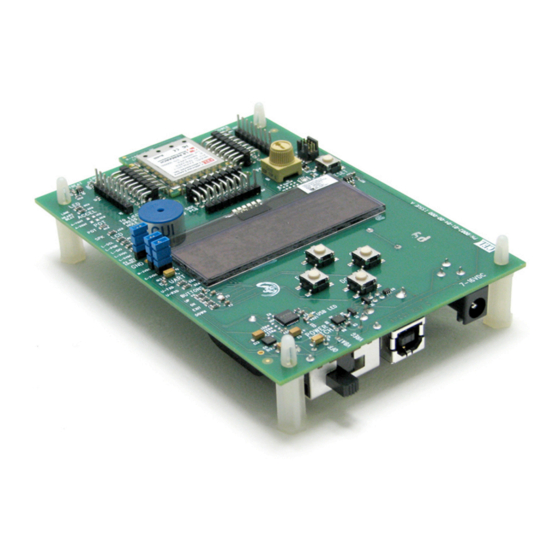
Overview of Controls and Features Power On LED APEX Module Potentiometer RESET Button JMP1 Jumper Ground JMP2 Jumper JMP3 Jumper LCD Display UP Button EXIT Button OK Button DOWN Button POWER AC/DC Switch Port POWER... - Page 9 Figure 1-2 RF Evaluation Board Components See Bill of Materials for component details Power is connected at the back of the interface board and can come from either batteries or an AC/DC power supply. The Power Management block on the interface board controls power distribution to the Apex module and peripheral components.
-
Page 10: Evaluation Test Menu
Evaluation Test Menu Once the board’s stack powers up, a menu is activated. Press the UP and DOWN buttons to cycle through the menu’s items. They’re described on the following pages: • Transmit Test — page 11 • Receive Test — page 17 •... -
Page 11: Chapter 2 - Transmit Test
Transmit Test In a Transmit Test, radio transmissions are sent from the module. A Transmit Test running on one module can be combined with a Receive Test running on a second module to test Range. The tests can be performed with or without additional test equipment as needed. -
Page 12: Channel
Channel The Channel Setting identifies the radio channel in use. 16 numbered channels (11-26) are defined by the IEEE 802.15.4-2003 standard in the 2.4GHz ISM band. Channels are spaced 5MHz apart. The default is channel 20. User Tip: Channels 15, 20, 25, and 26 for IEEE 802.15.4-2003 networks are usually available. -
Page 13: External Power Amplifier
Overdriving the input of the power amplifier can cause signal distortion and reduce the advantages of using the power amplifier. Boost mode transmit power values are available on CEL’s Apex data sheet: http://www.cel.com/pdf/datasheets/ZAXM-200Series.pdf External Power Amplifier An external power amplifier is provided with the module for better transmissions. -
Page 14: Packet Number
Packet Number Packet number (Packet #) is the number of packets transmitted in the PACKT send mode. The default is 100 packets. Select INFTY (infinity) to continue to send packets until your test is completed. You can select the packet number from the following ranges: •... - Page 15 3. Press DOWN arrow to display the first setting - Channel. Channel BACK EDIT 4. You can edit the settings by selecting from a list of values. For example, to edit the Channel setting, press OK. Channel UNDO • To view the choices for the setting, press UP or DOWN. •...
-
Page 16: Determining The Module's Maximum Power
How to Determine the Module’s Maximum Power 1. Scroll through the top menu to until Transmit Test is displayed. Transmit Test 2. Press OK to display Start Transmit. Start Transmit BACK START 3. Press DOWN until the Power setting is displayed. Leave the default setting: MAX: 3dB. -
Page 17: Chapter 3 - Receive Test
Receive Test A Receive Test is used to set up and test the module for receiving IEEE 802.15.4-2003 packetized data. By running a Transmit Test on one of the modules and a Receive Test on the other, you can perform a Range Test. The tasks described in this chapter include: •... -
Page 18: Channel
Channel Channel is the radio channel setting of the receiver module. To receive, it must match the channel setting of the transmitter module. The choice of channel settings ranges from 11 to 26. The default is 20. Channels are identified by number as defined by the IEEE 802.15.4-2003 standard. Boost Mode If Boost Mode is set to ON, sensitivity of the receiver is boosted by about 2 dBm. -
Page 19: Rssi Alert
RSSI alert If the Received Signal Strength Indicator (RSSI) is below the RSSI alert value, an alert will sound on the buzzer. The default is OFF. Values range from 10 down to -105, or OFF, which means no alert will sound. A typical value might be the receiver’s sensitivity as defined in the chip’s specification. - Page 20 5. Some settings may be edited. For example, to edit the PER alert setting, press OK. PER alert UNDO The PER alert setting is an error percentage threshold. If the error rate goes above this value, an alert sounds. • To view the choices for the setting, press UP or DOWN. •...
-
Page 21: Chapter 4 - Sleep Mode Test
Sleep Mode Test To conserve energy and extend battery life, Apex modules are designed to enter Sleep Mode when inactive. This test measures the current draw of the module while in sleep mode. You can test the current draw for two different sleep modes. •... - Page 22 3. Press OK to display Start Sleep. Start Sleep START BACK Press DOWN to display the Sleep mode setting. DEEP is the default. Sleep Mode DEEP BACK ALTER • To change the setting to IDLE, press OK. Sleep Mode IDLE BACK ALTER •...
-
Page 23: Chapter 5 - Energy Scan Test
Energy Scan Test In an Energy Scan Test, the individual transmission channels are scanned and the relative RSSI (Received Signal Strength Indication) energy per channel is displayed. User Tip: To determine actual values, run the Energy Scan Test using Ember’s InSight Desktop software. -
Page 24: Chapter 6 - Potentiometer Test
Potentiometer Test This test uses the Apex evaluation board’s potentiometer to test the voltage from the module’s analog-to-digital converter (ADC). 1. From the top menu, press UP or DOWN until Potentiometer is displayed. Potentiometer START 2. Press OK to start the test. POT: +0.6150 V The LCD displays a value for the potentiometer voltage changes. -
Page 25: Chapter 7 - Zigbee Wars Game
ZigBee Wars Game ZigBee Wars is a simple game that allows two or more players to challenge each other over a ZigBee network by communicating via the Apex modules. To play, all the Apex boards must set to the same channel. An easy way to ensure this is to press RESET. -
Page 26: Chapter 8 - Interface Board Settings
Interface Board Settings The Apex interface board has settings you can change and additional board functions you can test. To view or change these settings: 1. From the top menu, press UP or DOWN until Settings is displayed. Settings 2. Press OK to view the first setting. 3. -
Page 27: Self-Test
Self Test This is a series that can be run to test the board’s key components. 1. From the Settings menu, press UP or DOWN until Self Test is displayed. Self Test START 2. Press OK to start the tests, then follow the instructions displayed. The following components are tested: The buzzer sounds upon completion of each test. -
Page 28: Appendix 1 - Apex Module Features & Specifications
Appendix 1 Apex Module Features & Specifications Features • Ember™ EM250 platform • 16-bit onboard microprocessor • Designed for EmberZNet networks • 1mW to 100mW output, software configurable • 4000+ ft of range, line of sight • 130mA power consumption @ 100mW output •... -
Page 29: Pin Assignments
Apex Module Pin Assignments PIN 19: GROUND PIN 10: GROUND MISO GPIO 1 MOSI GPIO 0 LOADB GPIO 12 GPIO 16 GPIO 11 GPIO 15 RSTB GPIO 14 GPIO 13 GROUND GROUND GROUND PIN 28: GROUND PIN 1: GROUND PCB Trace Antenna Figure 9-1 Pin Assignments Name Type... - Page 30 GPIO11 DI/DO General Purpose Digital I/O, SC1 UART CTS, SC1 SPI master clock, or Capture Input A of Timer 2 GPIO12 DI/DO General Purpose Digital I/O, SC1 UART RTS, or Capture Input B of Timer 2 GPIO0 DI/DO General Purpose Digital I/O, SC2 SPI MOSI, or Capture Input A of Timer 1 GPIO1 DI/DO General Purpose Digital I/O, SC2 SPI MISO, SC2 I...
-
Page 31: Module Interface Pins
GPIO13 DI/DO General Purpose Digital I/O, Output A of Timer 2, or Capture Input A of Timer 1 GROUND Ground GROUND Ground Module Interface Pins Description Serial interface clock (internal pull-down.) MISO Serial interface (master in/slave out.) MOSI Serial interface (master out/slave in.) LOADB Serial interface load strobe GPIO16... -
Page 32: Appendix 2 - Interface Board Specifications
Appendix 2 Interface Board Specifications Jumper Settings There are three jumpers provided on each interface board. They’re provided to control the Power Amplifier (JMP1), the Apex Module (JMP2), and the interface board (JMP3). Name Label Function JMP1 PA REG ENABLE Connect to turn PA ON, disconnect to turn PA OFF JMP2 M–3VDC... - Page 33 No source code rights are granted to Purchaser or its customers. Purchaser agrees not to copy, modify, alter, translate, decompile, disassemble, or reverse engineer the CEL hardware (including without limitation any embedded software) or attempt to disable any security devices or codes incorporated in the hardware.
- Page 34 Mouser Electronics Authorized Distributor Click to View Pricing, Inventory, Delivery & Lifecycle Information: ZAXM-201-KIT-1...
Need help?
Do you have a question about the ZAXM-201 Series and is the answer not in the manual?
Questions and answers