Advertisement
Quick Links
How IR repeating works
The IR receiver is wired to
the IR hub which routes the
IR remote control
signal to IR emitters
at the IR receiver
And the emitter
CD player
repeats the IR signal
in the other room.
Be sure the emitter is attached directly over the component's IR receiver.
To locate the IR receiver, shine a flashlight into the unit and look for the
sensor.
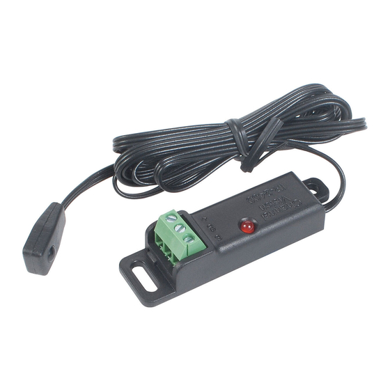
Specifications: (typical)
Voltage Requirements:
8 - 12 VDC
IR Freq. range supported:
30 kHz - 60 kHz
IR pickup range:
40 ft. @ 38kHz, 25 ft. @ 56kHz
IR receiver head dimensions:
0.65" x 0.35" x 0.25"
Color:
Black
Specifications subject to change without notice.
CHANNEL VISION
Limited Warranty
Channel Vision Technology will repair or replace any defect in material or
workmanship which occurs during normal use of this product with new or rebuilt
parts, free of charge in the USA, for two years from the date of original purchase.
This is a no hassle warranty with no mail in warranty card needed. This warranty
does not cover damages in shipment, failures caused by other products not
supplied by Channel Vision Technology, or failures due to accident, misuse,
abuse, or alteration of the equipment. This warranty is extended only to the
original purchaser, and a purchase receipt, invoice, or other proof of original
purchase date will be required before warranty repairs are provided.
Mail in service can be obtained during the warranty period by calling (800) 840-
0288 toll free. A Return Authorization number must be obtained in advance and
can be marked on the outside of the shipping carton.
This warranty gives you specific legal rights and you may have other rights
(which vary from state to state). If a problem with this product develops during or
after the warranty period, please contact Channel Vision Technology, your dealer
or any factory-authorized service center.
Directivity of IR Sensor
The effective receive distance of all IR receivers changes
Point an
when the IR remote control is not directly in front of the IR
sensor.
The graph below describes the performance of the IR sensor
device used in this Channel Vision IR receiver. Please note
that the graph below marks the distance as a percentage of
the maximum distance. So at 0º, the distance is 1.0 (or 100%)
and at 30º, the distance is 0.7 (or 70%) and so on.
Actual transmission distances are dependent upon frequency
of remote control (40kHz has max range) and luminosity of
remote control (i.e. Some remotes are brighter than others.)
Under ideal conditions,
ranges of >40 feet are
possible.
1.0
0.9
0.8
0.7
0.6
0.4
d
rel
Features:
Plasma Proof IR receiver
!
Status LEDs for IR signal indication
!
Versatile mounting accessaries: Install as
!
Very small receiver
In-cabinet tube type receiver
Unobtrusive desktop type receiver
500-153 rev C
0º
10º
20º
30º
40º
50º
60º
70º
80º
0.2
0
0.2
0.4
0.6
– Relative Transmission Distance
The IR-2400 includes these items:
CAUTION: DO NOT attempt to cut or extend this
wire. Doing so will prevent the unit from working.
IR receiver wire pinout
+V
(white dash or brown wire)
1 - IR receiver holster
1 - hole mount
1 - tabletop mount
End view
ribbon cable
Typical IR receiver
connections (ref only)
Sig
Tip
Collar
Gnd
+V
Ring
Advertisement

Related Manuals for Channel Vision IR-2400


Summary of Contents for Channel Vision IR-2400
- Page 1 CHANNEL VISION Limited Warranty Channel Vision Technology will repair or replace any defect in material or workmanship which occurs during normal use of this product with new or rebuilt parts, free of charge in the USA, for two years from the date of original purchase.
- Page 2 Using the IR-2400 with the P-1205 Mounting the IR receiver: Option 1 - Using the holster Mount the IR receiver to the TV or on a surface within line of sight of your remote control. Remove the backing from the tape and attach the IR receiver holster in the desired location.
Need help?
Do you have a question about the IR-2400 and is the answer not in the manual?
Questions and answers