Table of Contents
Advertisement
Quick Links
A.
GENERAL INFORMATION
The AT-WM is a pulse water meter, leak monitoring system that has been specifically designed to help achieve the
requirements of BREEAM 2011 (BRE Environmental Assessment Method).The AT-WM system will allow designers,
M&E contractors and developers to achieve the "Credit" available to reduce the impact of water leaks that may
otherwise go undetected. The system is designed to monitor water flowing through a pulse water meter. If the
volume of water reaches the pre-set limit (customer adjustable) the system can isolate the mains water pipe,
therefore limiting the amount of water and leak damage.
INSTALLATION ITEMS (NOT SUPPLIED)
Wall fasteners for surface mounting (four screws)
Rubber or elastomeric washers to seal at mounting points
Semi-flush recess flange (optional)
TOOLS REQUIRED
Drill or hole punch for electrical conduit entries
Phillips (cross-head) screwdriver
Small flat-head screwdriver
STORAGE
Keep the module in a dry place prior to installation to avoid possible damage to internal components.
B. PRODUCT INFORMATION
AT-WM—
12Vdc Regulated Supply 250mA (Polarity NonSpecific) PSU supplied.
Temperature—
85oC Max
Pressure—
0.35—10Bar
Flowrates—
ATWM will detect any flow rate greater than 0.5 litres per minute
S&S Northern Ltd. Wallace Francis House, Barnes Wallis Way, Buckshaw Village, Lancashire, PR7 7JN T. 01257 470983 www.snsnorthern.com
ATWM—Installation & Maintenance
Advertisement
Table of Contents

Related Manuals for S&S Northern ATWM


Summary of Contents for S&S Northern ATWM
- Page 1 12Vdc Regulated Supply 250mA (Polarity NonSpecific) PSU supplied. Temperature— 85oC Max Pressure— 0.35—10Bar Flowrates— ATWM will detect any flow rate greater than 0.5 litres per minute S&S Northern Ltd. Wallace Francis House, Barnes Wallis Way, Buckshaw Village, Lancashire, PR7 7JN T. 01257 470983 www.snsnorthern.com...
- Page 2 WIRING & PULLING Current IEE Regulations: AT-WM should be installed by a competent installer, in accordance with the recommendations laid down by the HVCA and sound engineering practice. D. PLUMBING INSTALLATION The diagrams will serve as a visual aid, but it is recommended that a competent plumber carries out the assembly and installation.
- Page 3 Plumb in the Water Meter and Solenoid Valve (if applicable) in line with the manufacturer’s instructions. Using wiring instructions above, connect each Meter and Valve assembly to the controller using a shielded 2 core 1.00mm2 copper cable. For longer runs, use a larger core size. Power the controller using the supplied transformer and open/close the valves to check they operate correctly.
- Page 4 J. WIRING FOR AT-RU1 RELAY UNIT DIN RAIL MOUNTABLE AT-RU1 CONNECTIONS Power Connections to Relay (Mains), 230Vac supply L = Live, N = Neutral, E = Earth Power Connections to Relay (Relay Valve), 230Vac supply L1= Live Close, L2= Live Open, N = Neutral, E = Earth Control Connections from AT-WM Controller 1= V (Valve) 2=C (Common) NOTE: Wiring should only be done by a qualified electrician NOTE: These diagrams are shown for one water meter and one solenoid valve.
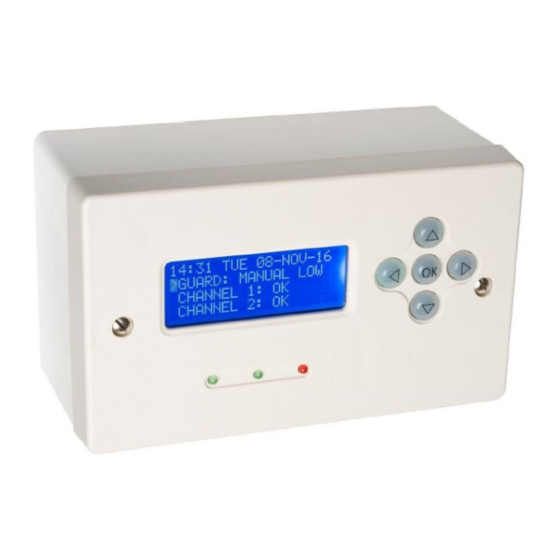
- Page 5 Page left and right to access other operating pages Override will show either Start Manual Override or Cancel Manual Override. Home This is the default screen, this screen displays date, time and system status. Modes Use OK to switch between Normal 2 guard and single Permanent High Mode. Also displays power source and me- ter readings.
- Page 6 L. AT-WM-C – SETTINGS GUIDE This document should be used as an additional guide to how to set up your AquiTron ATWM Major leak detection con- troller. Please fully read the AT-WM installation instructions for information on installing, connecting, and navigating around the menu system.
- Page 7 Any setting not mentioned in this guide is generally not required to setup the system and should be left as default. Allow 30-45 minutes to program and check each unit. If no button is pressed the system will time out and you will have to re-enter the menu. • ...
- Page 8 STEP 8 Flow Per – Press ok to cycle through the options. This is the setting the controller uses to measure the values en- tered in steps 2 and 3. [We generally use hour or half hour as these are the most granular setting and give the most pro- tection.
Need help?
Do you have a question about the ATWM and is the answer not in the manual?
Questions and answers