Table of Contents

Subscribe to Our Youtube Channel
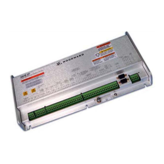
Related Manuals for Woodward 2301E-ST


Summary of Contents for Woodward 2301E-ST
- Page 1 Released Product Manual 26694 (Revision C, 11/2018) Original Instructions 2301E-ST Digital Electronic Load Sharing & Speed Control for Small Steam Turbines Installation and Operation Manual See Chapter 1 for part numbers/applications...
- Page 2 Revisions— A bold, black line alongside the text identifies changes in this publication since the last revision. Woodward reserves the right to update any portion of this publication at any time. Information provided by Woodward is believed to be correct and reliable. However, no responsibility is assumed by Woodward unless otherwise expressly undertaken.
-
Page 3: Table Of Contents
............29 HAPTER ERVICE AND ONFIGURATION ROCEDURES Introduction ..............................29 Configure Menu Descriptions ........................35 Save and Reset 2301E-ST Control......................43 Service Menu Descriptions ......................... 44 4. D ..................75 HAPTER ESCRIPTION OF PERATION 5. P .............. - Page 4 PPENDIX ODBUS OMMUNICATION 2301E-ST C ..................121 ONTROL PECIFICATIONS ........................122 EVISION ISTORY .......................... 123 ECLARATIONS The following are trademarks of Woodward, Inc.: Woodward The following are trademarks of their respective companies: Modbus (Schneider Automation Inc.) Windows (Intel Corporation) Woodward...
- Page 5 Figure 1-1. Functional Control Overview ....................10 Figure 2-1a. 2301E-ST Outline Drawing (8273-1013/-1014) ..............13 Figure 2-1b. 2301E-ST Outline Drawing, Hazardous Location Version ............. 14 Figure 2-2a. 2301E-ST Plant Wiring Diagram (sheet 1) ................15 Figure 2-2b. 2301E-ST Plant Wiring Diagram (sheet 2) ................16 ...
- Page 6 Released Manual 26694 2301E-ST Figure 4-10. Isochronous Load Sharing ...................... 85 Figure 5-1. Temporary Wiring for Transformer Phase Correction .............. 91 Figure 5-2. Droop Adjustment ........................93 Table 3-1. Calculated Generator Frequency Examples ................45 Table 3-2. Communication Error Code ....................... 71 ...
-
Page 7: Warnings And Notices
IMPORTANT - Designates an operating tip or maintenance suggestion. Ensure that personnel are fully trained on LOTO procedures prior to attempting to replace or service a 2301E-ST Control on a “live” running Turbine. All safety protective systems (overspeed, over Lockout/Tagout temperature, overpressure, etc.) must be in proper operational... -
Page 8: Electrostatic Discharge Awareness
Do not touch the components or conductors on a printed circuit board with your hands or with conductive devices. To prevent damage to electronic components caused by improper handling, read and observe the precautions in Woodward manual , Guide for Handling and Protection of Electronic Controls, 82715 Printed Circuit Boards, and Modules. -
Page 9: Regulatory Compliance
Released Manual 26694 2301E-ST Regulatory Compliance European Compliance for CE Mark These listings are limited only to those units bearing the CE Marking. Low Voltage Directive: Directive 2014/35/EU on the harmonisation of the laws of the Member States relating to the making available on the market of electrical equipment designed for use within certain voltage limits. - Page 10 Released Manual 26694 2301E-ST Nippon Kaiji Kyokai: Requirements specified in Chapter 1, Part 7 of Guidance for the approval and Type Approval of materials and equipment for Marine use and relevant Society’s Rules. RINA Rules for the Classification of Ships – Part C_Machinery, Systems and Fire Protection.
-
Page 11: Chapter 1. General Information
Like Woodward’s 2301A and 2301D line of controls, this control is housed in a sheet metal chassis and consists of a single printed circuit board. To facilitate unit retrofits, the 2301E-ST’s I/O terminals are located in the same general location as Woodward’s 2301A line of controls. This control is designed to perform the speed and load control functions of a small steam turbine package. -
Page 12: Applications
2301E-ST Applications The 2301E-ST is a field-configurable control designed to perform the basic speed and load control functions for single-valve steam turbines. It can be configured to allow a user to match the control’s functionality to the application. Configuration and service (dynamic adjustments made) is done via a laptop computer, connected to the control’s RS-232 communications port and utilizing Woodward’s... -
Page 13: References
Manual 26694 2301E-ST References The following publications contain additional product or installation information on Load Sharing and Speed Controls and related components. They can be obtained from the Woodward website (www.woodward.com/publications) or ordered from any Woodward office. Manual Title 25070... -
Page 14: Chapter 2. Installation
Chapter 2. Installation Introduction This chapter contains general installation instructions for the 2301E-ST control. Power requirements, environmental precautions and location considerations are included to determine the best location for the control. Additional information includes unpacking instructions, electrical connections and an installation check-out procedure. -
Page 15: Figure 2-1A. 2301E-St Outline Drawing (8273-1013/-1014)
Released Manual 26694 2301E-ST Figure 2-1a. 2301E-ST Outline Drawing (8273-1013/-1014) Woodward... -
Page 16: Figure 2-1B. 2301E-St Outline Drawing, Hazardous Location Version
Released Manual 26694 2301E-ST Figure 2-1b. 2301E-ST Outline Drawing, Hazardous Location Version Woodward... -
Page 17: Figure 2-2A. 2301E-St Plant Wiring Diagram (Sheet 1)
Released Manual 26694 2301E-ST Figure 2-2a. 2301E-ST Plant Wiring Diagram (sheet 1) Woodward... -
Page 18: Figure 2-2B. 2301E-St Plant Wiring Diagram (Sheet 2)
Released Manual 26694 2301E-ST Figure 2-2b. 2301E-ST Plant Wiring Diagram (sheet 2) Woodward... -
Page 19: Figure 2-2C. 2301E-St Plant Wiring Diagram (Notes)
Released Manual 26694 2301E-ST Figure 2-2c. 2301E-ST Plant Wiring Diagram (notes) Woodward... -
Page 20: Electrical Connections
Multiple direct connections of a shield to earth risk high levels of current to flow within the shield (exception, see note below on cabinet installations). Shields can be grounded at both ends (2301E-ST and load) if the cable length is sufficiently short (within a cabinet) to prevent ground loop current in the shield. -
Page 21: Figure 2-3. Installation Of Wiring Into Terminal
Power Supply Connections (Terminals 48-49) The 2301E-ST requires a voltage source of 18 to 40 Vdc, with a current capacity of at least 900 mA for operating power. If a battery is used for operating power, an alternator or other battery charging device is necessary to maintain a stable supply voltage. - Page 22 The Load Sharing Lines provide an analog communication path between compatible controls. The 2301E-ST provides an internal relay for connecting the Load Sharing Signal to the internal circuitry at the appropriate times. When the internal relay is closed, a green LED will illuminate between terminals 9 and 10.
- Page 23 Released Manual 26694 2301E-ST Start/Unload Contact (Terminal 36) Terminal 36 functions as the control’s External Start/Unload contact input. When an external start command is given (a closed contact state) and all shutdown conditions have been cleared, the control will cycle through its configured start routine. If all shutdown conditions have not been cleared the unit will not begin to cycle through its start routine.
- Page 24 Manual 26694 2301E-ST Contact Inputs (Terminal 39–41) The 2301E-ST has three other discrete input channels that are available for use. These contacts are configurable and can be programmed to perform one of the following functions: IDLE - RATED SPEED When the state of this contact is open the speed reference moves toward the programmed IDLE speed setpoint at its own configured rate set in service menus.
- Page 25 27(shield) as shown in Figure 2-2a. If a second optional MPU is utilized, connect it to terminals 28, 29, and 30 (shield) as shown in Figure 2-2a. Note that the 2301E-ST controller’s software program must be correctly configured to sense and use the second MPU input within its controller algorithms. If the 2301E- ST controller is configured to sense two MPU speed sensors, it will utilize its high-signal-select (HSS) voting logic to select a speed signal to control.
- Page 26 Released Manual 26694 2301E-ST Any of the four relays can be programmed to function as a level switch. When programmed as a level switch the relay will change state when the selected parameter reaches the programmed level (energizes when value is higher the programmed level). The following is a list of the level switches: ...
- Page 27 The control’s two serial communication ports are used to configure and service the unit. These ports are on a common return and are isolated ports. The RS-232 serial communication service port communicates using either the 2301E-ST Toolkit Service Tool or the Control Assistant software. Refer to Figure 2-2 for plant wiring information.
-
Page 28: Figure 2-4. Rs-232 Pin Assignments For Serial Communication Cable
Released Manual 26694 2301E-ST RS-232 See Figure 2-4 for cable connection. 2301D-ST Figure 2-4. RS-232 Pin assignments for Serial Communication Cable RS-422 See Figure 2-5 for termination and cable connection example. Figure 2-5. Typical RS-422 Communications Connections Woodward... -
Page 29: Figure 2-6. Rs-422 Terminator Locations
Released Manual 26694 2301E-ST Termination For RS-422, termination should be located at the receiver when one or more transmitters are connected to a single receiver. When a single transmitter is connected to one or more receiver, termination should be at the receiver farthest from the transmitter. Figure 2-6 is an example. -
Page 30: Installation Check-Out Procedure
Figure 2-8. Alternate Multipoint Wiring Using Shielded Twisted-pair Cable without a Separate Signal Ground Wire Installation Check-out Procedure Once the 2301E-ST is installed, perform the following checkout procedure before beginning the start-up adjustments in Chapter 4. Visual Inspection Check the linkage between the actuator and the valve on the steam turbine for looseness or binding. -
Page 31: Chapter 3. Service And Configuration Procedures
This chapter contains information on control configurations, setting adjustments and the use of Woodward’s Control Assistant software tool. Because of the variety of installations, system and component tolerances, the 2301E-ST must be tuned and configured for each system to obtain optimum performance. Refer to Chapter 4 for start-up settings, adjustments and instructions. - Page 32 Follow these Steps to Communicate with the Control: Step 1: Download the Control Assistant software from www.woodward.com/software. Go to Start \ Programs \ Woodward \ Control Assistant \ Control Assistant. This is what the window should look like: Step 2: Click on icon shown below:...
- Page 33 Released Manual 26694 2301E-ST Step 3: An OPC connection will appear. Check the radio buttons as shown below and click on Connect. Step 4: An OPC connection will be made. Woodward...
- Page 34 Released Manual 26694 2301E-ST Step 5: When the communication is complete, the window should look as follows: Step 6: Minimize the SOS Servlink OPC Server program (don’t close it down). Step 7: Click on the icon in the Main Window. This will open up a WinPanel window, with all of the Service...
- Page 35 Released Manual 26694 2301E-ST Step 8: The Configure and Service Menu Tabs are located across the top, as seen below: Step 9: Scroll Arrows can be used to scroll left or right through the menu’s, as seen below: Step 10: This manual will explain each menu header and all of the variable tunables.
- Page 36 Released Manual 26694 2301E-ST To download the settings file, Open Control Assistant software and connect. Put the control into I/O lock by selecting the Lock I/O icon . This will cause an I/O lock and could shutdown the engine. BE CAREFUL! Answer Yes to Locking I/O question.
-
Page 37: Configure Menu Descriptions
Communications dialog. Configure Menu Descriptions The 2301E-ST has “5” Configure menus and “21” Service menus to simplify and protect control settings and their adjustments. All menus appear as pages, are arranged alphabetically and can be located by using the inspector’s arrow buttons located above the pages to scroll to the desired menu. -
Page 38: Figure 3-2. Configure: A**Spd, Load, Strt Options** Menu
Released Manual 26694 2301E-ST To enter the I/O Lock mode and enable configure changes, click on the I/O Lock icon on the Tool Bar. Because the values set in Configure are critical to turbine operation, it is not safe to operate the prime mover while these parameters are being configured. - Page 39 Released Manual 26694 2301E-ST 04 MPU MIN SPD LEVEL (RPM) dflt= 250.0 (0.0, 2000) Enter the minimum detectable speed level for the control. Below this level the MPU would be detected as failed and a trip will be issued. The MPU input signal must be at least 1.0 Vrms at the minimum speed level programmed.
- Page 40 Released Manual 26694 2301E-ST Using the wrong the gear teeth setting or the Speed Ratio Setting could cause an overspeed condition, resulting in damage to equipment, personal injury or death. 11 USE CRITICAL BAND? dflt=FALSE (FALSE, TRUE) Set to TRUE to use the critical speed avoidance logic. When the speed setpoint is within the band, the speed setpoint cannot be stopped.
-
Page 41: Figure 3-4. Configure: B**Discrete In Options** Menu
Released Manual 26694 2301E-ST 19 GEAR RATIO MPU2 dflt=1.0 (0.1, 10) Enter the result of the (MPU gear speed) / (turbine shaft speed) speed ratio. This value is used to determine the internal hertz-to-rpm relationship and is calculated by dividing the speed of the MPU gear by the speed of the turbine shaft. -
Page 42: Figure 3-5. Configure: C**Discrete Out Options** Menu
CONFIGURE: C**DISCRETE OUT OPTIONS** Figure 3-5. Configure: C**DISCRETE OUT OPTIONS** Menu The 2301E-ST has four discrete output driver channels. Terminals 44, 45, 46 and 47 are configurable and can be programmed to perform one of several functions (listed below). Any of the four relay drivers can also be programmed to function as a level switch. When programmed as a level switch the relay will change state when the selected parameter reaches the programmed level (energizes when value is higher the programmed level). - Page 43 Released Manual 26694 2301E-ST 05 RELAY 2 ENERGIZES (1-12) dflt=3 (1, 12) Select one of the following parameters for discrete output at terminals 45. 1=NOT USED 2=SHUTDOWN 3=ALARM 4=ELEC. OVERSPEED TRIP TEST 5=VALVE LIMITER IN CONTROL 6=SPEED PID IN CONTROL...
-
Page 44: Figure 3-6. Configure: D**Analog Input Options** Menu
Released Manual 26694 2301E-ST CONFIGURE: D**ANALOG INPUT OPTIONS** Figure 3-6. Configure: D**ANALOG INPUT OPTIONS** Menu 01 CONFIGURATION ERROR? dflt=FALSE (FALSE, TRUE) Displays a TRUE if any of the two analog inputs are set the same. Not Used and Monitor Signal Input can be set the same. -
Page 45: Save And Reset 2301E-St Control
(reverse acting actuators should always incorporate a mechanical ballhead backup governor). Save and Reset 2301E-ST Control. When the tuning or setting of parameters is complete, the values must be saved in the control’s non- volatile memory. Go to the Tool Bar and click the PROM icon for Save Values. -
Page 46: Service Menu Descriptions
Released Manual 26694 2301E-ST Service Menu Descriptions Figure 3-8. Watch Window Menu and Explorer (Service) A** DISPLAY ANALOG INFO ** Figure 3-9. Service: A** DISPLAY ANALOG INFO ** Menu This is a display group for general monitoring of the turbine. - Page 47 Released Manual 26694 2301E-ST 01 SPEED CONTROL STATUS displays the status of the speed control. Will display one of the following: READY FOR RESET READY TO START VALVE LIMITER SPEED PID RAMP AT IDLE SPEED AT MIN GOVERNOR SPEED AT IDLE SPEED...
-
Page 48: Figure 3-10. Service: B** Display Load Info ** Menu
Released Manual 26694 2301E-ST B** DISPLAY LOAD INFO ** Figure 3-10. Service: B** DISPLAY LOAD INFO ** Menu This menu is used for general monitoring of the generator information. 01 LOAD CONTROL STATUS displays generator load control mode. Will display one of the following:... -
Page 49: Figure 3-11. Service: C** Shutdown ** Menu
03 POWER UP SHUTDOWN (1) displays the status of power up shutdown. Shutdown is detected when the power supply to the 2301E-ST is turned off. 04 OVERSPEED (2) displays the status of overspeed trip. Shutdown is detected when the turbine reaches an overspeed. -
Page 50: Figure 3-12. Service: D** Alarm ** Menu
Released Manual 26694 2301E-ST 06 ANALOG INPUT #1 FAIL (4) displays the status of Analog Input #1 (if configured). A failed input is detected when the analog #1 exceeds the following ranges: Input Set For: Low Trip Point High Trip Point 4–20 mA... - Page 51 Released Manual 26694 2301E-ST 02 FIRST ALARM displays the cause of the first alarm. If the control has an alarm condition, this menu item indicates the first alarm: NO ALARMS ANALOG INPUT #1 FAIL ANALOG INPUT #2 FAIL LOAD SENSOR FAIL...
-
Page 52: Figure 3-13. Service: E** Speed Dynamics ** Menu
Released Manual 26694 2301E-ST E** SPEED DYNAMICS ** Figure 3-13. Service: E** SPEED DYNAMICS ** Menu This menu gives the operator the ability to tune the dynamic adjustments. Dynamic adjustments are settings that affect the stability and transient performance of the turbine. There are two sets of dynamics provided. -
Page 53: Figure 3-14. Control Gain As A Function Of Speed Error
Released Manual 26694 2301E-ST Figure 3-14. Control Gain as a Function of Speed Error Woodward... -
Page 54: Figure 3-15. Typical Transient Response Curves
Released Manual 26694 2301E-ST Figure 3-15. Typical Transient Response Curves 06 USE ON LINE DYNAMICS? dflt=FALSE (FALSE, TRUE) Set to TRUE when selecting the ON LINE dynamics feature when the 52G GENERATOR BREAKER contact input is closed. Woodward... - Page 55 Released Manual 26694 2301E-ST 07 ON LINE PROP GAIN dflt=5.0 (0.01, 100.0) Determines how fast the control responds to an error in turbine speed from the speed-reference setting. The Proportional Gain is used to provide stable control of the turbine in a loaded condition.
-
Page 56: Figure 3-16. Service: F** Remote Speed Control** Menu
Released Manual 26694 2301E-ST F** REMOTE SPEED CONTROL ** Figure 3-16. Service: F** REMOTE SPEED CONTROL** Menu THIS MENU IS USED FOR THE REMOTE SPEED CONTROL LOGIC. The operation of two kinds of remote speed setting is possible for the control. One is the control by the analog input. Another is the control from Modbus. -
Page 57: Figure 3-17. Service: G** Speed Setting ** Menu
Released Manual 26694 2301E-ST G** SPEED SETTING ** Figure 3-17. Service: G** SPEED SETTING ** Menu OVERSPEED RATED ZERO IDLE SPEED TEST SPEED LIMIT CRITICAL SPEED ELECTRICAL BAND OVERSPEED TRIP LEVEL OPERATING RANGE MINIMUM MAXIMUM GOVERNOR GOVERNOR Figure 3-18. Speed Relationships This menu is used for setting up the speed set points of the turbine. -
Page 58: Figure 3-19. Service: H** Process Control ** Menu
Released Manual 26694 2301E-ST 08 RAISE SLOW RATE (RPM/S) dflt=10.0 (0.0, 1000) Enter the raise speed rate (rpm/second). This is the rate the speed setpoint moves when using the RAISE SPEED / LOAD discrete input until the Raise / Lower Time Delay has expired. At this time the Raise Fast Rate takes over. - Page 59 Released Manual 26694 2301E-ST THIS MENU IS USED FOR THE PROCESS CONTROL OF THE TURBINE. 01 PROCESS CONTROL ENABLED Displays the state of the process control. TRUE means the Process Control is enabled, FALSE means it is disabled. 02 USE PROCESS CONTROL?
-
Page 60: Figure 3-20. Service: I** Overspeed Test ** Menu
Released Manual 26694 2301E-ST 13 PROCESS DERIVATIVE RATIO dflt=100.0 (0.01, 100.0) Enter the process PID derivative ratio value. This value is used to set process control response. 14 PROCESS CNTRL DEADBAND dflt=0.01 (0.01, 5.0) Enter the process control deadband value. This value is used to set the deadband the process control will respond to. -
Page 61: Figure 3-21. Service: J** Failed Mpu Override** Menu
Released Manual 26694 2301E-ST 05 TURBINE SPEED (RPM) displays actual turbine speed in rpm. 06 SPEED REF (RPM) displays turbine speed setpoint in rpm. J** FAILED MPU OVERRIDE ** Figure 3-21. Service: J** FAILED MPU OVERRIDE** Menu THIS MENU IS USED FOR SETTING THE MPU OVERRIDE LOGIC. -
Page 62: Figure 3-23. Service: L* Valve Limiter Set ** Menu
Released Manual 26694 2301E-ST THIS MENU IS USED TO SETUP THE SYNCHRONIZER LOGIC. 01 ENBL SYNC INPUT displays whether the sync input is being used. If it is TRUE, the SYNC INPUT can be used. This should be activated in menu: Configure D** ANALOG INPUT OPTIONS 02 SYNC INPUT SCALE (%/V) dflt=0.7 (0.1, 5.0) -
Page 63: Figure 3-24. Service: M** Load Sensor And Droop ** Menu
Released Manual 26694 2301E-ST M** LOAD SENSOR AND DROOP ** Figure 3-24. Service: M** LOAD SENSOR AND DROOP ** Menu THIS MENU IS USED TO SET UP THE GENERATOR LOAD CONTROL PARAMETERS. 01 USE LOAD SENSOR? dflt=FALSE (FALSE, TRUE) Set to TRUE to use the built in generator load sensor for generator applications or FALSE when using control for pump, blower, or compressor applications. -
Page 64: Figure 3-25. Service: N** Act Linearization ** Menu
Released Manual 26694 2301E-ST 09 KW CALIBRATION GAIN dflt=10.0 (5.0, 40.0) Adjust until the KW reading for the load sensor output matches the external instrumentation readings. 10 LOAD TIME (KW/SEC) dflt=20.0 (1.0, 600.0) Set this value for loading rate. This sets the rate at which the Load Ramp will increase for soft loading. - Page 65 Released Manual 26694 2301E-ST 03 Y-2 VALUE dflt=10.0 (-10.0,110.0) Output point #2 of actuator linearization curve, in percentage. 04 X-3 VALUE dflt=20.0 (-10.0,110.0) Input point #3 of actuator linearization curve, in percentage. (Must be less than the ‘X-4 Value’) 05 Y-3 VALUE dflt=20.0 (-10.0,110.0)
-
Page 66: Figure 3-26. Service: O** Actuator Calibration ** Menu
Figure 3-26. Service: O** ACTUATOR CALIBRATION ** Menu Before initial operation or after a turbine overhaul where any actuator or valve travel may have been affected, the below Valve Calibration procedure will allow the 2301E-ST to be calibrated to the valve. 01 CALIBRATION ENABLE dflt=FALSE (FALSE, TRUE) Set to TRUE to calibrate the actuator or valve. -
Page 67: Figure 3-27. Service: P** Analog I/O Settings ** Menu
Released Manual 26694 2301E-ST P** ANALOG I/O SETTINGS ** Figure 3-27. Service: P** ANALOG I/O SETTINGS ** Menu This section calibrates the analog inputs and selects the parameter to be sent to the analog output driver and the desired scaling of the output. -
Page 68: Figure 3-28. Service: Q** Discrete Out Settings ** Menu
Q** DISCRETE OUT SETTINGS ** Figure 3-28. Service: Q** DISCRETE OUT SETTINGS ** Menu The 2301E-ST has four discrete output driver channels. Terminals 44, 45, 46 and 47 are configurable and can be programmed to perform one of the following functions. - Page 69 Released Manual 26694 2301E-ST 03 RELAY 1 LEVEL SELECT FOR displays the level function selected for terminal 44. 04 RELAY 1 ON LEVEL dflt=0.0 (-32000.0, 32000.0) Enter the level switch ON setting in engineering units. There is an ON and an OFF setting for each level switch option.
-
Page 70: Figure 3-29. Service: R** Display D_I/O Status ** Menu
Released Manual 26694 2301E-ST 16 RELAY 4 SELECTED AS displays the function selected for terminal 47. This relay is selected in the configure menu - C**DISCRETE OUT OPTIONS** 17 RELAY 4 LEVEL SW (1-7) dflt=1 (1, 7) Select one of the following parameters for discrete output at terminals 47 when it was selected as a level switch. -
Page 71: Figure 3-30. Service: S** Hardware Output Test ** Menu
Released Manual 26694 2301E-ST 07 DISCRETE INPUT G indicates status of discrete input G. 08 DISCRETE INPUT H indicates status of discrete input H. 09 DISCRETE OUTPUT #1 indicates status of discrete output #1. 10 DISCRETE OUTPUT #2 indicates status of discrete output #2. -
Page 72: Figure 3-31. Service: T** Comm Port (232) ** Menu
Released Manual 26694 2301E-ST 10 DISCRETE OUTPUT #2 displays the state of discrete output #2. 11 TURN ON DO-3 dflt=FALSE (FALSE, TRUE) Set to TRUE to turn ON the relay driver output #3. If test is finished, it should set to FALSE. - Page 73 ILLEGAL DATA Amount of data requested from slave was too large for slave to return in a VALUE single response. Woodward maximum is 118 registers The following are displayed only. CHECKSUM Error in the checksum. Can indicate link quality and/or noise problems.
-
Page 74: Figure 3-32. Service: U** Application Info ** Menu
Released Manual 26694 2301E-ST 16 NETWORK ADDRESS dflt=1 (1, 247) Set the Network Address input defines the slave block address on the Modbus network. The network address may depend on master device allowable addresses. 17 ENABLE MODBUS CONTROL dflt=FALSE (FALSE, TRUE) When set TRUE you are able to control using Modbus. - Page 75 ILLEGAL DATA Amount of data requested from slave was too large for slave to return in a VALUE single response. Woodward maximum is 118 registers. The following are displayed only. CHECKSUM Error in the checksum. Can indicate link quality and/or noise problems.
- Page 76 Released Manual 26694 2301E-ST 2=ODD 3=EVEN 12 PARITY IS SET FOR Shows the parity setting. 13 DRIVER IS SET FOR RS 422 14 TIME OUT (SEC) dflt=4.0 (0.0, 100.0) Set the Time-out Number of Seconds input defines the Modbus link dead time allowed before a link error occurs.
-
Page 77: Chapter 4. Description Of Operation
This chapter provides an overview of the features and operation of the 2301E-ST Load Sharing and Speed Control. The 2301E-ST Load Sharing and Speed Control uses a 32 bit microprocessor for all control functions. All control adjustments are made with an external computer that communicates with the control via a serial RS-232 port. -
Page 78: Figure 4-1. Basic Operational Architecture
Released Manual 26694 2301E-ST A P P LY P O W E R S E LF TE S T R U N 2301D -S T S TA R T W atch W indow C oinfigure M ode? O P E N "C onfigure" M enu O P E N "S ervice"... -
Page 79: Figure 4-2. Automatic Start-Up
This allows the operator to heat soak the turbine at various speeds. To continue the ramp, manually close the Speed Raise Contact. If for some reason the turbine shuts down, due to a 2301E-ST shutdown, and the Run and Start contact inputs are closed, a toggle on the Reset contact will initiate the start sequence. -
Page 80: Figure 4-3 Semi-Automatic Start-Up
Released Manual 26694 2301E-ST Semi-automatic Start. The Speed Reference will increase up to the rated speed reference after the Start Command is issued. The valve reference and actuator demand are controlled by the raise / lower contact inputs. Figure 4-3 is an example of a semiautomatic start sequence. -
Page 81: Figure 4-4 Manual Start-Up
Released Manual 26694 2301E-ST Manual Start The Speed Reference will increase up to the rated speed reference after the Start Command is issued. The speed of the turbine is controlled by the trip and throttle valve or control valve until turbine speed reaches speed reference. - Page 82 2 mA or greater the 22 mA, the control will shut down. Over Speed Test The 2301E-ST’s Over Speed test Function allows an operator to increase turbine Function speed above its rated operating range to periodically test turbine electrical and/or mechanical over speed protection logic and circuitry.
-
Page 83: Figure 4-5. Critical Speed Avoidance Band
KW Droop / Actuator KW Droop or Actuator Position Droop mode. Position Droop The 2301E-ST should be connected to the generator through the internal Operation load sensor using the PTs and CTs. When using the optional 52G BREAKER discrete input is open, Droop will be the control mode. In the Droop mode, the load sensor provides feedback to the speed control to decrease the speed reference based on load. - Page 84 Released Manual 26694 2301E-ST Process Control Process Control The process control can be configured to control any system process, related to or affected by turbine speed or load. Typically this controller is used as a turbine inlet or exhaust pressure controller. The process control is a PID controller that compares a 4–20 mA process signal with the...
-
Page 85: Figure 4-6. Paralleling System
Released Manual 26694 2301E-ST 2301D-ST LOAD VALVE DEM AND SPEED kW SENSOR M ATCHING REFERENCE CIRCUIT CIRCUIT INLET Turbine Generator LOAD SHARING LINE STEAM TURBINE CB AUX CONTACTS EXHAUST LOAD SIGNAL Figure 4-6. Paralleling System An auxiliary contact on the generator breaker connected to the discrete input is used to select speed and load control operation. -
Page 86: Figure 4-7. Droop Mode
Released Manual 26694 2301E-ST Figure 4-7. Droop Mode Droop is the speed reduction, expressed in percentage that occurs when the generator is fully loaded. With a given droop setting, a generator set will always produce the same power output at a particular speed or frequency. -
Page 87: Figure 4-8. Isochronous Mode
Released Manual 26694 2301E-ST Figure 4-8. Isochronous Mode Figure 4-9. Droop/Isochronous Load Figure 4-10. Isochronous Load Sharing Sharing Woodward... - Page 88 Released Manual 26694 2301E-ST Droop/Isochronous Droop/isochronous load sharing combines the first two modes. All Load Sharing on an generator sets in the system, except one, are operated in the droop mode. Isolated Bus The one unit not in droop is operated in the isochronous mode. It is known as the swing machine.
-
Page 89: Chapter 5. Pre-Start And Start-Up Procedures
2301E-ST Chapter 5. Pre-Start and Start-up Procedures Introduction This chapter provides an overview of the start-up procedures and operation of the 2301E-ST Load Sharing and Speed Control. Read this entire procedure before starting the prime mover. Start-up Adjustments Complete the Installation Procedure in Chapter 2 and the Service and Configuration Procedures in Chapter 3. -
Page 90: Dynamic Adjustment
INTEGRAL GAIN. Speed Sensor Check The 2301E-ST accepts a signal from one (or optionally two) passive magnetic pickup unit (MPU) speed sensors to sense turbine rotor speed. These speed sensor inputs are limited to a frequency range of 100 to 24 950 Hz (90 to 20 000 rpm) and a voltage range of 1.7–35 Vac (a voltage level above 2.7 Vac is... -
Page 91: Current Transformer (Ct) Phasing Check
Released Manual 26694 2301E-ST With proper MPU, gear size and MPU-to-gear clearance, speed measurement should be capable down to 100 Hz. Check the speed sensor for visible damage. Standard MPU clearance is recommended to be between 0.25 and 1.0 mm (0.010 and 0.040 inch) at the closest point. Make sure that the gear has less than 0.5 mm (0.020 inch) diametric run out. -
Page 92: Phase Correction Procedure
Watch Window sheet for B** DISPLAY LOAD INFO ** sheet and observe 02 LOAD SENSOR INPUT (KW) Load Sensor calibration and monitoring. Since the kW calibration cannot be completed until the phasing is correct, the value shown is for reference only. The Load Sensor of the 2301E-ST will only read a small negative value. - Page 93 Released Manual 26694 2301E-ST Figure 5-1. Temporary Wiring for Transformer Phase Correction Shut down the prime mover. HIGH VOLTAGE—The current transformers can develop dangerously high voltages. Do not disconnect a current transformer while the prime mover is running unless temporary 0.5 Ω, 20 W resistors are installed as shown in Figure 5-1 and all load is removed.
-
Page 94: Load Calibration Adjustment
It may be necessary to reduce the load signal reading of each unit in the system to as low as 3 volts in cases of extremely poor system dynamics. If your system requires a load signal reading as low as 3 volts, consult Woodward for suggestions for possible remedies. Woodward... -
Page 95: Droop Adjustment
Released Manual 26694 2301E-ST Droop Adjustment Because of the calculation available in the control, the droop percentage entered will result in the correct speed change if the KW sensor is properly calibrated. The droop percent is automatically corrected for load gain voltage values. The speed trim range can be configured to stop the speed reference at 100% load, or if a remote reference source is used its range can be set to give no load to full load limits. -
Page 96: Chapter 6. Troubleshooting
Released Manual 26694 2301E-ST Chapter 6. Troubleshooting Introduction The following troubleshooting guide is an aid in isolating trouble to the control box, actuator, plant wiring, or elsewhere. Troubleshooting beyond this level is recommended ONLY when a complete facility for control testing is available. -
Page 97: Control Test And Calibration
Control Test and Calibration General Conduct the following checks on the 2301E-ST. Then verify the functioning of set points and adjustments. Connect a computer to the communication port. Start the Control Assistant software in accordance with the instructions in Chapter 3. Verify correct voltage and polarity on the power supply input of the control. - Page 98 (respond). Prime mover will not start. Make resistance checks at the actuator. Actuator not moving to start Coil resistance on Woodward actuators steam position. is approximately 35 Ω. (Read with leads at terminals 13 and 14 disconnected.) Shutdown cause.
- Page 99 Check the magnetic pickup output after operating at rated voltage at speeds above idle—at least speed for some time. 1.0 Vrms. If magnetic pickup should fail and the override failed speed signal circuit is disabled, the 2301E-ST will call for maximum steam. Woodward...
- Page 100 If the problem cannot be resolved by these checks, it will be necessary to remove the 2301E-ST from the switchgear. Temporarily mount it next to the prime mover and connect only a battery, magnetic pickup and actuator to the control (use a separate battery placed next to the prime mover).
- Page 101 Released Manual 26694 2301E-ST Symptom Cause Solution Necessary external wires not properly If stability occurs when the control is shielded (continued). mounted next to the prime mover, return the control to the switchgear. Run new magnetic pickup, actuator, and battery power lines.
-
Page 102: Chapter 7. Communications
The Modbus communication port, as defaulted from the factory, is not programmed. Although this port is not programmed it continue to update all information to all registers. This allows the 2301E-ST to be monitored but not controlled from an external device. By simply connecting a monitoring device, configured to communicate through Modbus, and to the 2301E-ST’s defaulted protocol settings (parity,... -
Page 103: Modbus Function Codes
Service Mode, if required. The 2301E-ST control is programmed to function as a slave unit only. As a slave unit, the 2301E-ST will only respond to a transaction request by a master device. The 2301E-ST can directly communicate with a DCS or other Modbus supporting device on a single communications link, or through a multi-dropped network. -
Page 104: Port Adjustments
ST as signed 16 bit integer values. Since Modbus can only handle integers, values that require a decimal point in the Modbus Master Device are multiplied by a scaling constant before being sent by 2301E-ST. See Appendix B for defaulted communication constants and ranges. -
Page 105: Analog Reads
Modbus function code 4, which involves reading selected input registers. Analog Writes Holding registers are analog values that are writeable to the 2301E-ST. These values can also be read by a device performing an error check. An example of an analog write value would be a direct speed setpoint as opposed to raise and lower commands. -
Page 106: For More Modbus Information
Released Manual 26694 2301E-ST For More Modbus Information Detailed information on the Modbus protocol is presented in “Reference Guide PI-MBUS-300” published by AEC Corp./Modicon Inc., formerly Gould Inc. To implement your own source code, you must register with Modicon. Registration includes purchasing document PI-MBUS-303 and signing a non-disclosure agreement. -
Page 107: Chapter 8. Product Support And Service Options
An Authorized Independent Service Facility (AISF) provides authorized service that includes repairs, repair parts, and warranty service on Woodward's behalf. Service (not new unit sales) is an AISF's primary mission. A current list of Woodward Business Partners is available at www.woodward.com/directory. -
Page 108: Returning Equipment For Repair
All repair work carries the standard Woodward service warranty (Woodward Product and Service Warranty 5-01-1205) on replaced parts and labor. -
Page 109: Replacement Parts
The unit serial number, which is also on the nameplate Engineering Services Woodward offers various Engineering Services for our products. For these services, you can contact us by telephone, by email, or through the Woodward website. Technical Support ... -
Page 110: Technical Assistance
2301E-ST Technical Assistance If you need to contact technical assistance, you will need to provide the following information. Please write it down here before contacting the Engine OEM, the Packager, a Woodward Business Partner, or the Woodward factory: General Your Name... -
Page 111: Appendix A. Service/Configuration Chart
Released Manual 26694 2301E-ST Appendix A. Service/Configuration Chart CONFIGURE PROGRAMMED DEFAULT TUNABLE RANGE MENU VALUE VALUE MIN. MAX. A**SPD LOAD STRT OPTIONS** 01 Rated Speed (RPM) 3600.0 32000.0 02 Enter Rated/Max Load (KW) 1000 30000 03 Gen Freq Iis 50 Hz? - Page 112 Released Manual 26694 2301E-ST 10 Relay 4 Selected For Monitor 11 Reset Clears Trips? FALSE FALSE TRUE D**ANALOG INPUT OPTIONS** 01 Configuration Error? Monitor 02 Sel AI #1 Function (1-6) 03 Display AI #1 Function Monitor 04 Sel AI #1 Type (1-4)
- Page 113 Released Manual 26694 2301E-ST 06 System Load 0-3(Vdc) = Monitor 07 Load Sharing Bias (%) = Monitor C** SHUTDOWNS ** 01 Shutdown Status Monitor 02 First Shutdown Monitor 03 Power Up Shutdown (1) Monitor 04 Overspeed (2) Monitor 05 MPU Fail (3)
- Page 114 Released Manual 26694 2301E-ST F** REMOTE SPEED CONTROL ** 01 Remote Control Mode Monitor 02 Rmt/Proc Slw Rate (RPM/S) 1000.0 03 Rmt Stpt Deadband (RPM) 100.0 04 Rmt Stpt Fst Rate (RPM/S) 10.0 1000.0 05 Rmt 2nd Deadband (RPM) 10.0 100.0...
- Page 115 Released Manual 26694 2301E-ST I** OVERSPEED TEST ** 01 Overspeed Test Status Monitor 02 Overspeed Test Enable FALSE FALSE TRUE 03 Elec Overspeed Trip Setpt 4032.00 0.00 32000.00 04 Elec Overspd Trip Test Monitor 05 Turbine Speed(Rpm) Monitor 06 Speed Ref(Rpm)
- Page 116 Released Manual 26694 2301E-ST 10 Load Time (KW/SEC) 20.00 1.00 600.00 11 Enable Fast Load Rate FALSE FALSE TRUE 112 Fast Load Time (KW/SEC) 60.00 1.00 600.00 13 Fast Ramp Load (%) 80.00 1.00 110.00 14 Load Sharing Gain 0.20 0.01...
- Page 117 Released Manual 26694 2301E-ST 03 Input #1 Max Value (Unit) 100.00 -32000.0 32000.0 04 Analog In #1 Units Monitor 05 Display AI #2 Function Monitor 06 Input #2 Min Value (Unit) 0.00 -32000.0 32000.0 07 Input #2 Max Value (Unit) 100.00...
- Page 118 Released Manual 26694 2301E-ST 13 Internal L/S Relay K1 Monitor S**HARDWARE OUTPUT TEST** 01 Enable Hardware Test FALSE FALSE TRUE 02 Hardware Test Mode Monitor 03 AO Force Value (4–20 mA) 04 Analog Out (mA) Monitor 05 Anout, 4 mA Offset -100.0...
- Page 119 Released Manual 26694 2301E-ST 02 LINK ERROR Monitor 03 Error Percent Monitor 04 Error Number Monitor 05 BAUD RATE 06 BAUD RATE IS SET FOR Monitor 07 DATA BITS 08 DATA BITS ARE SET FOR Monitor 09 STOP BITS 10 STOP BITS ARE SET FOR...
-
Page 120: Appendix B. Modbus Communication List
Released Manual 26694 2301E-ST Appendix B. Modbus Communication List This Modbus Communication List is applicable for software revision 5418-6351. Table B-1. Modbus Communication List for Software Revision 5418-6351 Boolean Writes Address Description 0:0001 Modbus Controlled Shutdown 0:0002 Modbus Alarm Acknowledge... - Page 121 Released Manual 26694 2301E-ST 1:0010 Analog Input #2 Failed 1:0011 Load Sensor Failed 1:0012 Load Share Line Failed 1:0013 Speed PID In-Control 1:0014 Remote Speed Setpoint Enabled 1:0015 Speed Reference Lower Limit 1:0016 Speed Reference Raise Limit 1:0017 Load Sharing Enabled...
- Page 122 2301E-ST First Out Trip Indication The integer loaded into the 2301E-ST’s “Trip First Out” indication register 3:0001 indicates the first event sensed which caused the controller to shutdown. Refer to Table B-1 for integer-to-event relationship. Table B-2. Trip First Out Indication...
-
Page 123: 2301E-St Control Specifications
Released Manual 26694 2301E-ST 2301E-ST Control Specifications 8273-1013 – 2301 ST Woodward Part Numbers: 8928-5014 – Control Assistant Power Supply Rating: 18-36 Vdc (SELV) Power Consumption: Less than or equal to 20 W nominal Weight: 1.75 kg / 3.86 lb. -
Page 124: Revision History
Added new Declaration of Conformity Changes in Revision A— Updated Figure 1-1 to show second MPU & Modbus RS-442 port. Updated Figure 2-1a to show 2301E-ST. Added outline drawing of hazardous locations model (Figure 2-1b). Enlarged/clarified Figures 2-2a/b/c. -
Page 125: Declarations
Released Manual 26694 2301E-ST Declarations Woodward... - Page 126 Email and Website—www.woodward.com Woodward has company-owned plants, subsidiaries, and branches, as well as authorized distributors and other authorized service and sales facilities throughout the world. Complete address / phone / fax / email information for all locations is available on our website.
Need help?
Do you have a question about the 2301E-ST and is the answer not in the manual?
Questions and answers