Table of Contents
Advertisement
Advertisement
Table of Contents

Related Manuals for Woodward SPM-D2-10


Summary of Contents for Woodward SPM-D2-10
- Page 1 37615C SPM-D2-10 Synchronizing Unit Manual From Release 7.10-1 Manual 37615C...
- Page 2 Provides other helpful information that does not fall under the warning or caution categories. Woodward reserves the right to update any portion of this publication at any time. Information provided by Woodward is believed to be correct and reliable. However, Woodward assumes no responsibility unless otherwise expressly undertaken.
-
Page 3: Copyright And Disclaimer
The manufacturer cannot be held liable for any resulting damage, the user alone bears the risk for this. As to the appropriate use of the device: The technical data and tolerances specified by Woodward have to be met. -
Page 4: Table Of Contents
SPM-D2-10- (Power Supply: 24 Vdc) ................... 10 SPM-D2-10/X (Power Supply: 24 Vdc) ..................11 SPM-D2-10/N (Power Supply: 90 to 250 Vac or 120 to 375 Vdc) ..........12 SPM-D2-10/XN (Power Supply: 90 to 250 Vac or 120 to 375 Vdc) ..........13 Reference Point ............................ - Page 5 Product Service Options .......................... 63 Returning Equipment for Repair ......................63 Packing a Control .......................... 64 Return Authorization Number RAN ....................64 Replacement Parts ..........................64 How to Contact Woodward ........................65 Engineering Services ..........................66 Technical Assistance ..........................67 © Woodward Page 5/68...
- Page 6 Figure 4-14: Controller - SPM-D2-10/X & XN - three-position controller ................19 Figure 4-15: Controller - SPM-D2-10/X & XN - analog controller output - speed/frequency ..........20 Figure 4-16: Controller - SPM-D2-10/X & XN - analog controller output - voltage ..............20 Figure 5-1: Control loop ................................
-
Page 7: Chapter 2. General Information
Manual 37615C SPM-D2-10 - Synchronizing Unit Chapter 2. General Information The SPM-D2-2-10 is a synchronizing unit. The following functions can be realized by using the appropriate dis- crete inputs: Synchronization Synch-check Dead bus start The SPM-D2 starts as a standard unit that may have additional functions added with each package. The model of... -
Page 8: Chapter 3. Electrostatic Discharge Awareness
WARNING To prevent damage to electronic components caused by improper handling, read and observe the pre- cautions in Woodward manual 82715, Guide for Handling and Protection of Electronic Controls, Printed Circuit Boards, and Modules. Page 8/68 © Woodward... -
Page 9: Chapter 4. Installation
Manual 37615C SPM-D2-10 - Synchronizing Unit Chapter 4. Installation CAUTION A circuit breaker must be provided near to the unit and in a position easily accessible to the operator. This must also bear a sign identifying it as an isolating switch for the unit. -
Page 10: Wiring Diagrams
Manual 37615C SPM-D2-10 - Synchronizing Unit Wiring Diagrams ≡≡≡≡≡≡≡≡≡≡≡≡≡≡≡≡≡≡≡≡≡≡≡≡≡ SPM-D2-10- (Power Supply: 24 Vdc) lower SPEED raise Three-position controller lower VOLTAGE raise Three-position controller alternatively Generator voltage Reply: CB is open Enable CB Command: close CB Function: make- Readiness for operation contact Common (term. -
Page 11: Spm-D2-10/X (Power Supply: 24 Vdc)
Manual 37615C SPM-D2-10 - Synchronizing Unit SPM-D2-10/X (Power Supply: 24 Vdc) Voltage Current Voltage Current Speed Speed Speed Governor Governor Governor SPEED Analog controller VOLTAGE Analog controller Governing: alternatively - Frequency lower (f-) Generator voltage N.O. - Voltage lower (V-) -
Page 12: Spm-D2-10/N (Power Supply: 90 To 250 Vac Or 120 To 375 Vdc)
Manual 37615C SPM-D2-10 - Synchronizing Unit SPM-D2-10/N (Power Supply: 90 to 250 Vac or 120 to 375 Vdc) lower SPEED raise Three-positioncontroller L (90..250 Vac / 120..375 Vdc) lower VOLT AGE raise Three-positioncontroller alternatively Generator voltage Reply: CBis open EnableCB Com mand: closeCB N .O . -
Page 13: Spm-D2-10/Xn (Power Supply: 90 To 250 Vac Or 120 To 375 Vdc)
Manual 37615C SPM-D2-10 - Synchronizing Unit SPM-D2-10/XN (Power Supply: 90 to 250 Vac or 120 to 375 Vdc) Figure 4-4: Wiring diagram SPM-D2-10/XN © Woodward Page 13/68... -
Page 14: Reference Point
Manual 37615C SPM-D2-10 - Synchronizing Unit Reference Point ≡≡≡≡≡≡≡≡≡≡≡≡≡≡≡≡≡≡≡≡≡≡≡≡≡ Reference point Figure 4-5: Reference point Terminal Description Reference point: Neutral point of the three-phase system (3Ph4W) or neutral terminal of the voltage transformer (Measuring reference Sold.lug point); with three-conductor systems (3Ph3W), do not connect Power Supply ≡≡≡≡≡≡≡≡≡≡≡≡≡≡≡≡≡≡≡≡≡≡≡≡≡... -
Page 15: Measuring Inputs
≡≡≡≡≡≡≡≡≡≡≡≡≡≡≡≡≡≡≡≡≡≡≡≡≡ NOTE The SPM-D2-10 can only operate one circuit breaker. This limits the controller to operating one syn- chronization point. The voltage measured by terminals 23/24 is the synchronization reference voltage for the generator (variable system) voltage measured by terminals 20/21. The synchronization refer- ence voltage can be the mains or busbar voltage. -
Page 16: Mains/Busbar
Manual 37615C SPM-D2-10 - Synchronizing Unit Mains/Busbar Synchronizing voltage Figure 4-9: Measuring inputs - synchronization voltage NOTE Connection corresponding to the mains configuration (see wiring diagram). Terminal Measurement Description Connection to the measuring circuit voltage corresponding to variant , or ... -
Page 17: Discrete Inputs
Manual 37615C SPM-D2-10 - Synchronizing Unit Discrete Inputs ≡≡≡≡≡≡≡≡≡≡≡≡≡≡≡≡≡≡≡≡≡≡≡≡≡ CAUTION Please note that the maximum voltages which may be applied at the discrete inputs are defined as fol- lows. Voltages higher than those specified will damage the hardware! Maximum input range: +/-18 to 250 Vac. -
Page 18: Relay Outputs
Ready for operation 2.5 mm² NC (break contact) Controller Outputs ≡≡≡≡≡≡≡≡≡≡≡≡≡≡≡≡≡≡≡≡≡≡≡≡≡ The SPM-D2-10 is equipped with two three-position controllers (made of a form C and form A relay) for raising and lowering voltage and frequency. The SPM-D2-10/X & SPM-D2-10/XN controllers can be configured for dif- ferent output signals. -
Page 19: Spm-D2-10/X & Spm-D2-10/Xn
Manual 37615C SPM-D2-10 - Synchronizing Unit SPM-D2-10/X & SPM-D2-10/XN SPM-D2-10/X & SPM-D2-10/XN controller outputs can be configured for the following signals and may re- quire the use of an external jumper between terminals. Versions NOTE Only one controller output may be configured as three-step controller. -
Page 20: Figure 4-15: Controller - Spm-D2-10/X & Xn - Analog Controller Output - Speed/Frequency
Manual 37615C SPM-D2-10 - Synchronizing Unit Setting: 'ANALOG' and 'PWM' (analog controller) - Frequency controller Speed / power controller Speed / power controller Speed / power controller Figure 4-15: Controller - SPM-D2-10/X & - analog controller output - speed/frequency Type... -
Page 21: Chapter 5. Description Of Functions
Manual 37615C SPM-D2-10 - Synchronizing Unit Chapter 5. Description of Functions Function Tables ≡≡≡≡≡≡≡≡≡≡≡≡≡≡≡≡≡≡≡≡≡≡≡≡≡ Table for Terminal 6 if Configured "Enable control" The unit may be used as an SPM-A by energizing terminal 6. The status of the discrete inputs "Reply: CB is open" (terminal 4) and "Enable CB" (terminal 3) are displayed on the face of the controller via the LEDs "Gen CB - ON"... -
Page 22: Table 5-2: Operating Conditions - Terminal 6 = "Off
Table for Terminal 6 if Configured "OFF" The SPM-D2-10 and 10/X may be used as an ASG 410+ by de-energizing terminal 6. The status of the discrete inputs "Reply: CB open" (terminal 4) and "Enable CB" (terminal 3) is displayed on the face of the controller via the LEDs "GCB closed"... -
Page 23: Additional Conditions
Manual 37615C SPM-D2-10 - Synchronizing Unit Additional Conditions The functions described above for terminal 6 are dependent upon the conditions listed in Table 4-3 in conjunction with the states of the discrete inputs. The desired function must also be enabled when configuring the control unit. -
Page 24: Control Inputs
Manual 37615C SPM-D2-10 - Synchronizing Unit Control Inputs ≡≡≡≡≡≡≡≡≡≡≡≡≡≡≡≡≡≡≡≡≡≡≡≡≡ Terminal 6 = "Enable control" Enable/Release CB Terminal 3 If terminal 3 is energized, the operation of the power circuit breaker is en- abled. Circuit breaker operation will be disabled when terminal 3 is de- energized. -
Page 25: Operating Conditions
Manual 37615C SPM-D2-10 - Synchronizing Unit Operating Conditions ≡≡≡≡≡≡≡≡≡≡≡≡≡≡≡≡≡≡≡≡≡≡≡≡≡ No Load Control The generator voltage and generator frequency are adjusted to the configured set point values. The generator cir- cuit breaker is open. Synchronizing Slip Frequency Synchronization The generator voltage and frequency will be adjusted to the synchronization reference voltage. The circuit breaker connection command is issued with consideration for the inherent delay of the circuit breaker. -
Page 26: Synch-Check
Manual 37615C SPM-D2-10 - Synchronizing Unit Synch-Check The controller can be utilized as a Synch-check module. Control functions are not performed. The "CB close" re- lay remains energized as long as the following conditions are met: The voltage differential is within the configured limit (screen "synchronization dV... -
Page 27: Control Outputs
Manual 37615C SPM-D2-10 - Synchronizing Unit Control Outputs ≡≡≡≡≡≡≡≡≡≡≡≡≡≡≡≡≡≡≡≡≡≡≡≡≡ Synchronization pulse: Energizing this relay will close the CB. The relay de-energizes after the clos- Command: Close CB S schließen ing pulse is issued. Exception: Synch-check operation mode. Terminals 14/15 Ready for operation The contact assembly is closed when the unit is ready for operation. -
Page 28: Analog Controller Outputs
Manual 37615C SPM-D2-10 - Synchronizing Unit Analog Controller Outputs ≡≡≡≡≡≡≡≡≡≡≡≡≡≡≡≡≡≡≡≡≡≡≡≡≡ The analog PID controller forms a closed-loop control loop together with the controlled system (usually a first- order lag element). The parameters of the PID controller (proportional-action coefficient K , derivative-action... - Page 29 Manual 37615C SPM-D2-10 - Synchronizing Unit Overshoot x : Highest transient set point value deviation during the transition from one steady-state condition to a new steady-state condition following modification of the disturbance variable or reference input variable (x m Op- ...
-
Page 30: Figure 5-3: Step Response - Controller Set-Up
Manual 37615C SPM-D2-10 - Synchronizing Unit Controller operated as a P-only controller = [screen setting: T (where T =0], T = 0). Increase gain K (P gain) until the control loop oscillates continuously at K Pcrit CAUTION If the unit starts to oscillate uncontrollably, perform an emergency shutdown and change the screen setting accordingly. -
Page 31: Chapter 6. Display And Operating Elements
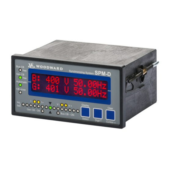
Manual 37615C SPM-D2-10 - Synchronizing Unit Chapter 6. Display and Operating Elements The foil of the front plate is made of coated plastics. All keys have been designed as touch-sensitive membrane switch elements. The display is a LC-display, consisting of 2 rows each with 16 characters, which are indirectly il- luminated red. -
Page 32: Brief Explanation Of The Leds And Push Buttons
Manual 37615C SPM-D2-10 - Synchronizing Unit Brief Explanation of the LEDs and Push Buttons ≡≡≡≡≡≡≡≡≡≡≡≡≡≡≡≡≡≡≡≡≡≡≡≡≡ LEDs No Description Function Bus CB Free Non-functional Gen CB Free Enable CB Automatic Automatic mode CB close Close command to the CB issued Synchroscope... -
Page 33: Leds
Manual 37615C SPM-D2-10 - Synchronizing Unit LEDs ≡≡≡≡≡≡≡≡≡≡≡≡≡≡≡≡≡≡≡≡≡≡≡≡≡ Bus CB Free Enable mains circuit breaker here: non-functional Color: green NOTE: This LED is non-functional, as this control is only designed to oper- ate one circuit breaker. Gen CB Free Enable power circuit breaker Color: green The LED "Gen CB Free"... - Page 34 Manual 37615C SPM-D2-10 - Synchronizing Unit Decrease frequency governor output Color: yellow Three position controller The "f-" LED indicates if the unit is outputting a pulse to decrease the fre- quency. The "f-" LED illuminates when the relay "speed lower" is energized.
-
Page 35: Push Buttons
Manual 37615C SPM-D2-10 - Synchronizing Unit Push Buttons ≡≡≡≡≡≡≡≡≡≡≡≡≡≡≡≡≡≡≡≡≡≡≡≡≡ Configuration may be performed by manually inputting the desired set points utilizing the pushbuttons and the LC display. In order to facilitate configuring the parameters, the push buttons have been enabled with an AUTOROLL function. -
Page 36: Lc Display
Manual 37615C SPM-D2-10 - Synchronizing Unit LC Display ≡≡≡≡≡≡≡≡≡≡≡≡≡≡≡≡≡≡≡≡≡≡≡≡≡ LC-Display LC-Display The two-line LC display outputs corresponding text messages and values de- pending on the mode that the SPM-D2 is operating. In the configuration mode, the monitoring parameters may be changed. When the SPM-D2- is in the automatic mode, the measured values are displayed. -
Page 37: Chapter 7. Configuration
Manual 37615C SPM-D2-10 - Synchronizing Unit Chapter 7. Configuration In order to configure the device via a PC/Notebook please proceed as follows. Install Toolkit and the USB Driver for the SPM-D2 from the CD that is provided with the product or from the webpage. -
Page 38: Configure Basic Data
Manual 37615C SPM-D2-10 - Synchronizing Unit CAUTION Please note that configuration only should be done when the system is not in operation. NOTE Please note the parameter list located in Appendix C of this manual. The configuration mode is initiated by pressing the "Digit" and "Cursor" pushbuttons simultaneously. The control is advanced through the various parameters by pressing the "Select"... -
Page 39: Password Protection
Manual 37615C SPM-D2-10 - Synchronizing Unit Password Protection The unit is equipped with a three-level code hierarchy. This permits access to different levels of selected parame- ters and configuration privileges. A distinction is made between: Code level 0 (CL0) - User: Third party This code level does not allow access to the parameters. - Page 40 Manual 37615C SPM-D2-10 - Synchronizing Unit Parameter 10417 Factory default settings Yes/No Factory default settings Yes ....Parameter 1701 (Set factory default values) will become visible. No ....Parameter 1701 (Set factory default values) will be hidden. Parameter 1701 Set factory default values...
-
Page 41: Configure Basic Settings
Manual 37615C SPM-D2-10 - Synchronizing Unit Configure Basic Settings ≡≡≡≡≡≡≡≡≡≡≡≡≡≡≡≡≡≡≡≡≡≡≡≡≡ WARNING The following values must be entered correctly to ensure proper monitoring of the generator. Failure to do so may lead to incorrect measuring of parameters resulting in damage to or destruction of the gen-... -
Page 42: Configure Controller
Manual 37615C SPM-D2-10 - Synchronizing Unit Generator set point voltage 50 to 440 V Parameter 5600 Gen. voltage The generator (variable system) voltage set point is entered in this screen. The volt- Setpoint 000V age controller will reference this value for no-load and isolated operations. -
Page 43: Frequency Controller
Manual 37615C SPM-D2-10 - Synchronizing Unit Frequency Controller The following screens are not found on the SPM-D2-10, SPM-D2-10/N. They utilize a three-position controller to regulate the frequency. The SPM-D2-10/X & SPM-D2-10/XN have the option to utilize multiple methods of fre- quency control. - Page 44 Manual 37615C SPM-D2-10 - Synchronizing Unit Frequency controller ON pulse minimum time 10 to 250 ms Parameter 5551 Freq. controller The frequency controller relay ON pulse is configured in this screen. The time peri- Time pulse>000ms od should be configured so that the frequency controller is able to respond accurate- &...
- Page 45 Manual 37615C SPM-D2-10 - Synchronizing Unit PWM signal level 3.0 to 10.0 V Parameter 5210 f control output This configuration screen only appears if the frequency controller is configured as Level PWM 00,0V PWM type! The voltage amplitude for the PWM signal is configured here.
- Page 46 Manual 37615C SPM-D2-10 - Synchronizing Unit Maximal value frequency controller 0 to 100% Parameter 5209 f control output This parameter permits the user to tailor the controller to their specific needs. This (max.) 000% value specifies the upper limit of the analog frequency controller output.
-
Page 47: Voltage Controller
Manual 37615C SPM-D2-10 - Synchronizing Unit Voltage Controller The following screens are not found on the SPM-D2-10, SPM-D2-10/N. They utilize a three-position controller to regulate the voltage. The SPM-D2-10/X & SPM-D2-10/XN have the option to utilize multiple methods of voltage control. - Page 48 Manual 37615C SPM-D2-10 - Synchronizing Unit Voltage controller ON pulse minimum time 20 to 250 ms Parameter 5651 Volt. controller The voltage controller relay ON pulse is configured in this screen. The time period Time pulse>000ms should be configured so that the voltage controller is able to respond accurately. The &...
- Page 49 Manual 37615C SPM-D2-10 - Synchronizing Unit Initial voltage controller state 0 to 100% Parameter 5608 V control output This parameter is the set point for the voltage when the voltage controller is not ena- Init.state 000% bled. The value will be entered as a percentage that relates to the minimum and max- &...
- Page 50 Manual 37615C SPM-D2-10 - Synchronizing Unit P-gain voltage controller 1 to 240 Parameter 5610 Volt. controller The proportional-action coefficient K indicates the closed-loop control system Gain Kp gain. By increasing the gain, the response is increased to permit larger corrections to &...
-
Page 51: Synchronization
Manual 37615C SPM-D2-10 - Synchronizing Unit Synchronization ≡≡≡≡≡≡≡≡≡≡≡≡≡≡≡≡≡≡≡≡≡≡≡≡≡ Configure Synchronization CAUTION Please consider that the unit does not have an internal rotating field monitoring. The unit assumes always a clockwise phase rotation direction of all voltage systems, which are meas- ured. - Page 52 Manual 37615C SPM-D2-10 - Synchronizing Unit Phase matching control ON / OFF Parameter 5729 Phase matching ON ....The synchronization is performed with phase matching control and the power circuit breaker closure is dependent upon the phase angle (refer to "Phase Matching Synchronization" on page 25). Only the parame- ters relating to phase matching are displayed.
-
Page 53: Synchronization Time Monitoring
Manual 37615C SPM-D2-10 - Synchronizing Unit Phase-angle-zero-control gain 1 to 36 Parameter 5505 Phase matching This configuration screen only appears, if the phase matching control is configured Gain Phase matching control = ON When phase matching control is enabled, this gain determines how much the output signal is changed depending on phase difference. -
Page 54: Dead Bus Start
Manual 37615C SPM-D2-10 - Synchronizing Unit Dead Bus Start ≡≡≡≡≡≡≡≡≡≡≡≡≡≡≡≡≡≡≡≡≡≡≡≡≡ Closing the circuit breaker may be performed even if synchronization voltage is not present. The close CB com- mand is issued if the input "Enable CB" (terminal 3) is energized and input "Reply: CB is open" (terminal 4) sig- nals an open circuit breaker. -
Page 55: Password Configuration
Manual 37615C SPM-D2-10 - Synchronizing Unit Password Configuration ≡≡≡≡≡≡≡≡≡≡≡≡≡≡≡≡≡≡≡≡≡≡≡≡≡ NOTE Once the code level is entered, access to the configuration menus will be allowed for two hours or until another password is entered into the control. If a user needs to exit a code level then code level CL0 should be entered. -
Page 56: Chapter 8. Commissioning
Manual 37615C SPM-D2-10 - Synchronizing Unit Chapter 8. Commissioning DANGER - HIGH VOLTAGE When commissioning the unit, please observe all safety rules that apply to the handling of live equip- ment. Ensure that you know how to provide first aid in the event of an uncontrolled release of energy and that you know where the first aid kit and the nearest telephone are. - Page 57 Manual 37615C SPM-D2-10 - Synchronizing Unit Check the status of all control and auxiliary inputs and the appropriate LEDs on the front foil of the unit. Check the status of all control and auxiliary outputs as well as the setting of the controller outputs.
-
Page 58: Appendix A. Dimensions
Manual 37615C SPM-D2-10 - Synchronizing Unit Appendix A. Dimensions Configuration port Configuration port Front view Back plate mount option (please order brackets P/N 8923-1023) Bottom view 108.8 Back view with connecting terminals 48 48 25 25 0 1 1 24 24... -
Page 59: Appendix B. Technical Data
Manual 37615C SPM-D2-10 - Synchronizing Unit Appendix B. Technical Data Measuring voltage ---------------------------------------------------------------------------------------------- Measuring voltage Rated value (V ) / ........[1] 63/110 Vac rated [4] 230/400 Vac Maximum value V (UL/cUL) ..... [1] max. 150 Vac Ph-Ph [4] max. 300 Vac Rated voltage V .......... - Page 60 Manual 37615C SPM-D2-10 - Synchronizing Unit Housing ----------------------------------------------------------------------------------------------------------- Type ..................... APRANORM DIN 43 700 Dimensions (W × H × D) ................144 × 72 × 122 mm Front cutout (W×H) ..............138 [+1.0] × 68 [+0.7] mm Wiring ................Screw-type terminals depending on plug connector 1.5 mm²...
-
Page 61: Appendix C. List Of Parameters
Manual 37615C SPM-D2-10 - Synchronizing Unit Appendix C. List of Parameters Product number P/N _____________________________ Rev _______________________________ Version SPM-D2-10 ____________________________________________________________ Project _____________________________________________________________________ Serial number S/N _______________ Date ______________________________ Parameter Default Adjustment range Customer settings Option 100/400V; 1/5 A setting CONFIGURE GENERAL PARAMETERS SPRACHE/LANGUAGE ... - Page 62 Manual 37615C SPM-D2-10 - Synchronizing Unit Parameter Default Adjustment range Customer settings Option 100/400V; 1/5 A setting Volt. controller Gain Kp 0.1 to 99.9 15.0 Parameter Standard Adjustment range Customer settings Option 100/400V; 1/5 A setting V control output refer to table under...
-
Page 63: Appendix D. Service Options
≡≡≡≡≡≡≡≡≡≡≡≡≡≡≡≡≡≡≡≡≡≡≡≡≡ If a control (or any part of an electronic control) is to be returned to Woodward for repair, please contact Wood- ward in advance to obtain a Return Authorization Number. When shipping the unit(s), attach a tag with the fol- lowing information: ... -
Page 64: Packing A Control
Stuttgart [+49 (0) 711-789 54-510]. They will help expedite the processing of your order through our distributors or local service facility. To expedite the repair process, contact Woodward in advance to obtain a Return Authori- zation Number, and arrange for issue of a purchase order for the unit(s) to be repaired. No work can be started un- til a purchase order is received. -
Page 65: How To Contact Woodward
For assistance outside Germany, call one of the following international Woodward facilities to obtain the address and phone number of the facility nearest your location where you will be able to get information and service. You can also contact the Woodward Customer Service Department or consult our worldwide directory on Wood- ward’s website (www.woodward.com) for the name of your nearest Woodward distributor or service facility. -
Page 66: Engineering Services
Colorado, or from one of many worldwide Woodward offices or authorized distributors. Field engineers are expe- rienced on both Woodward products as well as on much of the non-Woodward equipment with which our prod- ucts interface. For field service engineering assistance, please contact us via our toll-free or local phone numbers, e-mail us, or use our website and reference field service. -
Page 67: Technical Assistance
Manual 37615C SPM-D2-10 - Synchronizing Unit Technical Assistance ≡≡≡≡≡≡≡≡≡≡≡≡≡≡≡≡≡≡≡≡≡≡≡≡≡ If you need to telephone for technical assistance, you will need to provide the following information. Please write it down here before phoning: Contact Your company ____________________________________________________ Your name _______________________________________________________ Phone number ____________________________________________________... - Page 68 Phone +49 (0) 711-789 54-510 Fax +49 (0) 711-789 54-101 stgt-info@woodward.com Homepage http://www.woodward.com Woodward has company-owned plants, subsidiaries, and branches, as well as authorized distributors and other authorized service and sales facilities throughout the world. Complete address/phone/fax/e-mail information for all locations is available on our website (www.woodward.com).
Need help?
Do you have a question about the SPM-D2-10 and is the answer not in the manual?
Questions and answers