Table of Contents
Advertisement
Quick Links
Thank you for purchasing this product.
Be sure to read this operation manual before use.
Handle this product in accordance with the explanations described in this manual.
After reading this operation manual, keep it with the warranty in a safe place.
If you find any unclear points in this manual, please contact your Sibata distributor.
SIBATA SCIENTIFIC TECHNOLOGY LTD.
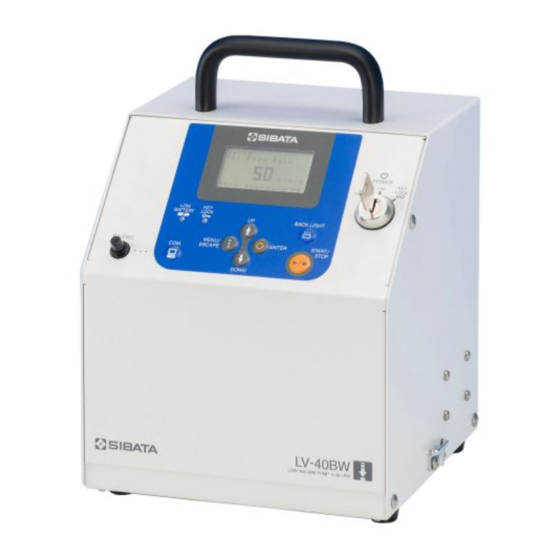
Low-Volume Pump
LV-40BW
Operation Manual
CODE 080800-045
Advertisement
Table of Contents

Related Manuals for Sibata LV-40BW


Summary of Contents for Sibata LV-40BW
- Page 1 Handle this product in accordance with the explanations described in this manual. After reading this operation manual, keep it with the warranty in a safe place. If you find any unclear points in this manual, please contact your Sibata distributor. SIBATA SCIENTIFIC TECHNOLOGY LTD.
-
Page 2: Table Of Contents
Contents Before Using the Product ··················································· 4 Product Overview ························································ 8 Features ····································································· 8 Installation ·································································· 9 Configuration ······························································ 9 Names of Parts ·········································································· 10 Control Panel ············································································· 11 Using Methods ·························································· 12 Using with an AC Power Supply ···················································· 12 Using with a DC Power Supply (Battery Unit) ···································... - Page 3 Operation Methods ···················································· 23 Overview of Screen Display ·························································· 23 Before Sampling ········································································ 25 7.2.1 Main Screen ········································································· 25 7.2.2 Main Menu ··········································································· 26 Sampling Start Stanby ································································· 40 7.3.1 Main Screen ········································································· 40 7.3.2 Main Menu ··········································································· 40 During Sampling ········································································ 41 7.4.1 Main Screen ·········································································...
-
Page 4: Before Using The Product
Use only the exclusive charger (BC-100B Battery Charger) and battery LV-40BW BU-24B BC-100B (BU-24B/BU-24L Battery Unit) for this product (LV-40BW Low-Volume Pump). BU-24L Do not use other batteries. Do not use this product or allow gases to be sucked into this product when it is near... - Page 5 BU-24L by this product, remove the BU-24B/BU-24L and BC-100B, and contact your Sibata distributor. Do not use this product in an abnormal state or allow it to be dismantled for repair by non-service personnel. Doing so might cause malfunction or accidents.
- Page 6 Do not use this product when the power cable is damaged or the plug inlet on LV-40BW BC-100B the power outlet is loose. Use in this state might cause fire or electric shock. Do not touch the power cable or power outlet with wet hands. Doing so might...
- Page 7 OFF, disconnect the power plug, and contact your Sibata distributor. Even in the event of a malfunction or other problem, Sibata shall not provide LV-40BW compensation for any data or records that the user failed to obtain or lost, or for any other direct or indirect damage or losses related to that data.
-
Page 8: Product Overview
The battery charger (sold separately) can charge up to three battery units simultaneously. * Battery unit There are two battery units exclusively for the LV-40BW: BU-24B and BU-24L. The BU-24B uses a lead storage battery, and the BU-24L uses a lithium iron phosphate battery. -
Page 9: Installation
This is the pump body. It is solely driven by an AC power supply. BU-24B/BU-24L Battery Unit This battery is exclusively for the LV-40BW (sold separately). Adding this unit can extend the pump's drive time. Up to three units can be added. * BC-100B Battery Charger This charger is exclusively for the BU-24B/BU-24L (sold separately). -
Page 10: 4.1 Names Of Parts
4.1 Names of Parts (sold separately) Back View (sold separately) (1) Handle (6) Fuse (11) Temperature sensor (2) Control Panel (7) Power cable inlet (12) Hose nozzle (13) Backup filter * (3) Receiving fixture (twist lock) (8) Exhaust port (4) Flow indicator fixing port * (9) Suction port (14) Charging confirmation lamp (5) Cooling fan... -
Page 11: Control Panel
Control Panel (1) Key switch : Power switch (2) RS-232C port : Data output terminal. This terminal has a black cap. (3) MENU/ESCAPE : Menu, escape key (4) ENTER : Enter key (5) UP : Key for incrementing set values (6) DOWN :... -
Page 12: Using Methods
Using a battery unit as a backup power supply When the LV-40BW pump is connected to an AC power outlet with the pump connected to a BU-24B/BU-24L, the pump will run on the AC power supply. However, when power supply is no longer supplied from the AC power supply due to a power failure, for example, electrical power is automatically supplied from the BU-24B/BU-24L. -
Page 13: How To Charge The Battery
The TF98 glass fiber filter PTFE binding is attached to the AN-200, NW-354 and C-30 (9.6 L/min). On other holders, the AP2005500 glass fiber filter is attached. How to Charge the Battery When the [LOW BATTERY] lamp on the LV-40BW lights, this indicates that the battery is about to expire. Charge the battery immediately. - Page 14 * If the [CHARGE] lamp does not change color to green even considerably after 15 hours of charging, a probable cause is a malfunctioning battery. Immediately disconnect the power cable, and contact your Sibata distributor. * Be sure to ground this product. Before inserting the power cable into the power outlet, be sure to ground this product beforehand.
-
Page 15: How To Connect The Pump To The Battery Unit
How to Connect the Pump to the Battery Unit When connecting the LV-40BW to the BU-24B/BU-24L or connecting two or three BU-24B/BU-24L units together, use the twist lock. (1) Stack the units to be connected. (2) Check that the knob on the twist lock is at the top position (at right angles towards the front). -
Page 16: How To Operate The Control Panel
LCD screen, followed by the main screen (preset flow rate). After this, the LV-40BW can be operated. When the key switch is turned right from the ON position, the keys are in a locked state. In this state, the switches on the panel sheet do not operate even if pressed. -
Page 17: How To View The Lcd
How to View the LCD Two types of screens are displayed on the LCD, the main and main menu screens. [1] Main Screen (1) Main item (2) Sub item (3) Item details display (4) Flow rate setting item display This is the basic screen that is displayed when the power is turned ON or an item is selected on the menu. -
Page 18: Basic Operations
Basic Operations This chapter describes the basic operations for running this pump. For detailed operations, or functions not described in this chapter, see the following chapters. (1) Turn the [POWER] switch key to the ON S e t u p S e t F l o w R a t e... -
Page 19: Timer Selection
Timer Selection When "5 Select Timer" is selected in the Setup sub-menu, a type of ON timer and OFF timer can be selected. There are three types of ON timers as shown below: Manual, Delay Time and Start Time. This is used to manually operate the pump. Sampling is started when [START/STOP] key is pressed in the main screen display. -
Page 20: Sampling Start Time Setting (On Timer)
Sampling Start Time Setting (ON Timer) When "2 Set ON Time" is selected in the Setup S e t u p menu, the sub-menu shown on the right is S e t T i m e D e l a y T i m e displayed and you can set the sampling start time 2 S t a r t... -
Page 21: Sampling Stop Time Setting (Off Timer)
Sampling Stop Time Setting (OFF Timer) When "3 Set OFF Time" is selected in the Setup S e t u p menu, the sub-menu shown on the right is S e t O F F T i m e R u n T i m e displayed and you can set the sampling stop time 2 S t o p... -
Page 22: Starting Sampling
[3] Total Flow Rate Timer Setting (Total Volume) When "3 Total Time" is selected, the digits of S e t u p O F F T i m e integer part is displayed highlighted as shown S e t T o t a l V o l u m e on the right. -
Page 23: Operation Methods
Operation Methods Overview of Screen Display [1] Main Screen (Before Sampling) When the pump is turned ON, "Setup Set Flow Rate" is initially displayed. The display changes in the order shown in the table below by pressing the [UP] and [DOWN] keys. When the display progresses to "Current Date and Time,"... - Page 24 Main Screen Display (Standby for Sampling Start) Display Description Displays the time remaining until start of sampling. Waiting Time Remaining ( See P40.) Waiting Set ON Time Displays the ON timer setting. ( See P40.) Main Menu (Standby for Start of Sampling) Only "Setup"...
-
Page 25: Before Sampling
Before Sampling 7.2.1 Main Screen [1] Setup Set Flow Rate (Suction Flow Rate Set Value) This displays the suction flow rate set value. S e t u p On the last line, for the actual volume flow rate, S e t F l o w R a t e "Actual VF"... -
Page 26: Main Menu
7.2.2 Main Menu 1 Last Data (Latest Measurement Value) The latest (previous) measurement value is displayed with the Last Data menu. When "1 Last Data" is selected in the main menu, the following sub-menu is displayed. Select the menu in the same way as for the main menu. - Page 27 Ambient BP. (Ambient Pressure) When "4 Ambient BP." is selected and the [ENTER] key is pressed, the Ambient BP. menu is displayed. When "MIN.," "MAX.," and "AVG." are respectively selected by the [UP] and [DOWN] keys and the [ENTER] key is pressed, the respective ambient pressure minimum value, maximum value and average value during sampling are displayed.
- Page 28 Sample Time (Sampling Time Warning) When the sampling time has exceeded ±1 L a s t D a t a hour of the preset time, the sampling time is S a m p l e T i m e W a r n i n g >...
- Page 29 3 Setup (Settings) When "3 Setup" is selected in the main menu, the following sub-menu is displayed. Select the menu in the same way as for the main menu. Press the [MENU/ESCAPE] key several times according to the screen display until the display returns to the main screen. Setup Menu Display Display Description...
- Page 30 Start Time (Start Time Timer Setting) When "2 Start Time" is selected and the S e t u p T i m e S e t S t a r t T i m e [ENTER] key is pressed, the set value of the sampling start time is displayed.
- Page 31 when the "month," "day," and "hours" settings are changed in order in the same way as "year," then the "minutes" setting is changed, and the [ENTER] key is pressed, the newly set values are entered. The screen returns to the Set OFF Time menu. * The setting range for "year"...
- Page 32 Setup – Select Timer (Timer Selection) When "5 Select Timer" is selected and the S e t u p [ENTER] key is pressed, the Select Timer S e l e c t T i m e r menu is displayed as shown on the right. : D e l a y T i m e O F F : R u n...
- Page 33 Setup – Set Flow Unit (Flow Rate Unit Setting) When "6 Set Flow Unit" is selected and the [ENTER] key is pressed, the Set Flow Unit menu is displayed. Select the respective menu by the [UP] and [DOWN] keys, and press the [ENTER] key.
- Page 34 Setup – Set Fault Stop (Fault Stop Setting) When "7 Set Fault Stop" is selected and the [ENTER] key is pressed, the Set Fault Stop menu is displayed. Select the respective menu by the [UP] and [DOWN] keys, and press the [ENTER] key.
- Page 35 1-minute intervals and power may no longer be recovered. * Even in the event of a malfunction or other problem, Sibata shall not provide compensation for any data or records that the user failed to obtain or lost, or for any other direct or indirect damage or losses related to that data.
- Page 36 6 Test (Device Check) When "6 Test" is selected in the main menu display, the following Test menu is displayed. Select the menu in the same way as for the main menu. Press the [MENU/ESCAPE] key several times according to the screen display until the display returns to the main screen. Test Menu Display Display Description...
- Page 37 Flow Rate (Suction Flow Rate Calibration) (1) Connect a "standard flowmeter" to the LV-40BW. (2) When "1 Flow Rate" is selected and the C a l i b r a t i o n [ENTER] key is pressed, the current S t a n d a r d standard temperature setting is displayed.
- Page 38 Ambient BP. (Ambient Pressure Sensor Calibration) Prepare a standard "ambient pressure gauge." C a l i b r a t i o n The port for measuring the ambient pressure is A m b i e n t B P . located on the rear panel (BARO.
- Page 39 After matching the pressure loss display to the readout value on the standard pressure gauge by pressing the [UP] and [DOWN] keys, press the [ENTER] key. Calibration input is accepted, and the screen returns to the Calibration menu. After calibration is finished, be sure to re-connect the tube to the filter. * After setting the numerical value, if the [MENU/ESCAPE] key is pressed before the [ENTER] key is pressed, the screen will return to the Calibration menu without the newly entered value being accepted.
-
Page 40: Sampling Start Stanby
Sampling Start Stanby 7.3.1 Main Screen [1] Waiting Time Remaining (Remaining Time Until Sampling Start) The time until sampling starts after the pump W a i t i n g started up is displayed. T i m e R e m a i n i n g When "OVER"... -
Page 41: During Sampling
During Sampling 7.4.1 Main Screen [1] Sampling Live Flow Rate (Instantaneous Flow Rate) The instantaneous flow rate of the pump is displayed. On the last line, for the actual volume flow rate, "Actual VF" is displayed, and for the volume flow rate after conversion to the standard state, the standard temperature and "Standard VF"... -
Page 42: Main Menu
7.4.2 Main Menu 2 Current Data (Current Value) When "2 Current Data" is selected in the main menu, the following sub-menu is displayed. Select the menu in the same way as for the main menu. Press the [MENU/ESCAPE] key several times according to the screen display until the display returns to the main screen. - Page 43 Pressure Drop (Filter Pressure Loss) When "5 Pressure Drop" is selected and the [ENTER] key is pressed, the Pressure Drop menu is displayed. When "MIN.," "MAX.," and "30sec AVG." are respectively selected by the [UP] and [DOWN] keys and the [ENTER] key is pressed, the respective filter pressure loss minimum value, maximum value and 30-second average value since sampling was started are displayed.
-
Page 44: After Sampling Is Stopped
Set Flow Rate (Suction Flow Rate Set Value) When "1 Set Flow Rate" is selected and the [ENTER] key is pressed, the preset flow rate is displayed. Set ON Time (ON Timer Set Value) When "2 Set ON Time" is selected and the [ENTER] key is pressed, one of the ON timers - Manual, Delay Time and Start Time - preset at "Select Timer"... -
Page 45: Flow Rate
Sampling Fault When sampling does not end normally, "FAULT" F i n i s h e d is displayed on the 2nd line, and the cause of the F A U L T P r e s s u r e r o p fault stop is displayed on the 3rd line. -
Page 46: Data Logging
Data Logging The measurement results of data logged in chronological order at 1-minute intervals (total flow rate, average flow rate, fluctuation coefficient, ambient pressure, pressure loss, ambient temperature, generation of warning) can be checked by using the LV-250/40B communications cable (sold separately) provided with the software. - Page 47 When the Battery Voltage Has Dropped to 21 V or Less During Operation by BU-24B/BU-24L (Sold Separately) Power Supply Fault ON Timer Selection Stop Setting Delay Time / Start Time ON(Default setting) The power voltage fault is displayed and pump operation is discontinued. Pump operation is continued even if the battery voltage drops.
-
Page 48: Fault Stop Function
When the Battery Voltage Has Dropped to 21 V or Less During Operation by BU-24B/BU-24L (Sold Separately) Power Supply OFF Timer Selection Fault Stop Setting Manual Run Time Stop Time Total Volume The power The power The power The power voltage fault is voltage fault is voltage fault is... -
Page 49: Troubleshooting
The housing is hot. Turn the power OFF, and wait for the housing to cool down. If this does not remedy the problem, contact your Sibata distributor. Keys cannot be pressed. KEY LOCK is lit. Turn the key switch to the ON position. -
Page 50: Specifications
Specifications LV-40BW Low-Volume Pump Item Code 080800-045 Suction Flow Rate 5.0 to 40.0 L/min Instantaneous Flow Rate 4.0 to 50.0 L/min Display Range Constant Flow Rate Operating 5.0 L/min: 5 to 35 kPa Range 10.0 L/min: 0 to 35 kPa 20.0 L/min: 0 to 22 kPa... -
Page 51: Related Products
12 Warranty If a Sibata product fails within 1 year from date of purchase, it will be repaired free of charge. To request repairs, contact your Sibata representative. Be sure to provide the item code, product name, model number, serial number, a description of the problem, and other relevant information. - Page 52 Note) Shape, dimensions, specifications, and other product information are subject to change without notice in the interest of product improvement to the extent that product functions and applications will not be impaired.
Need help?
Do you have a question about the LV-40BW and is the answer not in the manual?
Questions and answers