Table of Contents
Advertisement
Quick Links
CODE 090860-0341
090860-1041
O P E R A T I O N M A N U A L
Thank you for purchasing this product.
This operation manual describes precautions that are important for preventing accidents as
well as the procedures used to handle the product.
To ensure safety, read this operation manual and the attached warranty thoroughly before
use, and use the product correctly.
After reading this operation manual and the warranty, keep them in a safe place where
they can be referred to at any time.
Advertisement
Table of Contents

Subscribe to Our Youtube Channel
Related Manuals for Sibata MINIPUMP MP-EKNII Series


Summary of Contents for Sibata MINIPUMP MP-EKNII Series
- Page 1 CODE 090860-0341 090860-1041 O P E R A T I O N M A N U A L Thank you for purchasing this product. This operation manual describes precautions that are important for preventing accidents as well as the procedures used to handle the product. To ensure safety, read this operation manual and the attached warranty thoroughly before use, and use the product correctly.
-
Page 2: Table Of Contents
Table of Contents Before Use ..........................1 Safety Precautions ......................2 Product Overview ........................ 5 Features ..........................5 Names of Parts ........................6 How to Install the Battery ....................8 How to Remove the Battery ....................9 Wiring Methods ........................10 Charging Methods ...................... -
Page 3: Before Use
Every effort has been made to ensure that the information contained in this operation manual is correct. If you discover any errors or omissions, however, please contact your Sibata representative. The copyright of this operation manual belongs to Sibata Scientific Technology Ltd. -
Page 4: Safety Precautions
Safety Precautions The precautionary information that appears in this operation manual is for ensuring that the product is used safely and for preventing injury to you and other people and damage to equipment. It is all important for ensuring safety and so be sure to read it thoroughly before using the product and observe it during use. - Page 5 When the abnormality is judged to be caused by this product, remove the battery and contact your Sibata agent. Do not use this product in an abnormal state or allow it to be dismantled for repair by non-service personnel. Doing so might cause malfunction or accidents.
- Page 6 Doing so might damage the hardware, for example. Note that, should some nonconformity occur, SIBATA does not assume any liability whatsoever for compensation of data or content that could not be acquired or logged as a result, loss of data or other content, and other direct and indirect damages relating to the preceding.
-
Page 7: Product Overview
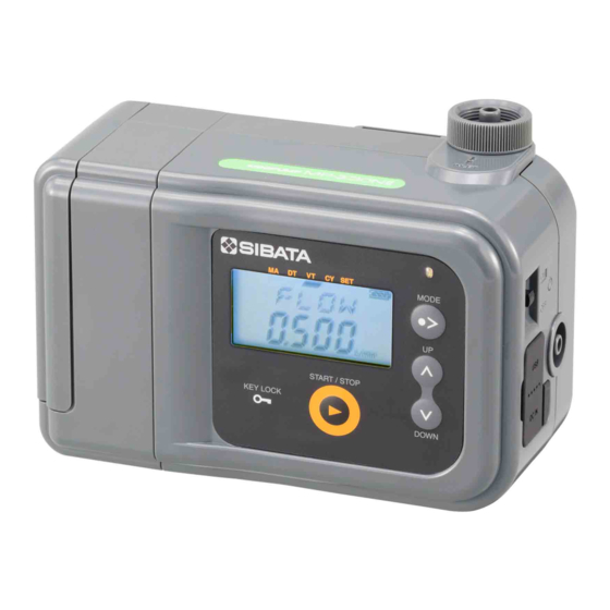
Product Overview The Mini Pump MP-Σ30KNⅡ and MP-Σ100KNⅡ are an ultra-lightweight, portable pump designed exclusively for sampling air, and features integrated flow measurement functions. The MP-Σ30KNⅡ has a flow rate range of 0.05 to 0.5 L/min, and the MP-Σ100KNⅡ has 0.1 to 1.5 L/min under highly-loaded condition. -
Page 8: Names Of Parts
Names of Parts MP-ΣNⅡ + LI-10KN (or DB-10N) Inside the rubber cover (1) Battery Holder or Battery Unit (8) Charging connector (LI-10KN only) (LI-10KN or DB-10N) (9) Hook (2) Model nameplate (10) Slide lock (3) Suction port (suction holder) (11) Tripod mounting hole (base) (4) Power switch (12) Power source connector (5) Exhaust port... - Page 9 Operation Panel (1) Operation display LED (5) START/STOP key (2) MODE key (6) KEY LOCK key (3) UP key (7) LCD screen (4) DOWN key The meanings of the operation display LED indications are as follows: flashing (green) - pump operating, flashing (red) - error occurred and pump operation stopped, and flashing (orange) - timer standing by or connecting to PC.
-
Page 10: How To Install The Battery
How to Install the Battery Fit the battery into the body while referring to the mounting position mark on the body. * Take care not to touch the electrodes. Installation position mark Body side "Click" "Click" Slide the battery towards the front, and make sure that it is fully fitted in as far as it can go. -
Page 11: How To Remove The Battery
How to Remove the Battery Before removing the battery, slide the slide lock on Slide lock the back of the body as shown in the figure to unlock the lock. With the slide lock unlocked, slide Remove in direction of the battery towards the rear to the arrow. -
Page 12: Wiring Methods
Wiring Methods When Used with the AC Power Source The pump can be operated by an AC power source by connecting the QC-10KN Quick Charger (sold separately) directly to the pump body. Also, the pump can be operated and the LI-10KN (sold separately) charged at the same time with the LI-10KN installed. -
Page 13: Charging Methods
Charging Methods The LI-10KN Battery Holder (sold separately) is charged using the QC-10KN Quick Charger (sold separately). As shown in the figure, the LI-10KN can be charged by connecting the QC-10KN to the pump body with the LI-10KN installed. Also, the LI-10KN has a charging connector. So, the battery itself can be charged by connecting the LI-10KN directly to the QC-10KN. -
Page 14: Installation And Piping Methods
Installation and Piping Methods Install the pump body on a flat location. When choosing an installation site, avoid humid locations or locations that are splashed with water, locations near fire or heat generating sources, and extremely dust locations. The pump body can also be mounted on a tripod. Insert the tripod screws into the tripod mounting hole on the base of the pump body. - Page 15 Suction Pressure A load (suction pressure) is applied to the pump by collected matter in the dust collector installed on the suction port. On each of the pump models, the maximum suction pressure is determined by respective flow rate. (See page 36 "Main Specifications.") Exceeding the specification range will cause malfunction; however, this pump does not have a function for measuring suction pressure.
-
Page 16: How To Install The Suction Holder
How to Install the Suction Holder The suction holder can be removed from the suction Turn in the direction of port by turning it counterclockwise. the arrow to remove. The filter element in the suction holder can be replaced by pulling lightly. Be sure to insert the filter element into the suction holder before installing the suction holder. -
Page 17: Preparing For Operation
Preparing for Operation Make sure that the wiring and piping have been properly connected. Turn ON the power switch on the side of the pump body. The version and flow rate conversion temperature value are displayed on screen, and the screen changes as follows. -
Page 18: Operation Modes
Operation Modes This pump has the following four operation modes. (1) Manual mode operation (See page 17.) Pressing the START/STOP key starts and stops pump operation. The only setup item provided is instantaneous flow rate. (2) Down timer mode operation (See page18.) Pressing the START/STOP key operates the pump for the preset time. -
Page 19: Manual Mode
Manual Mode LED display Flashing conventions Press the MODE key until the MA segment of the mode display bar lights. The instantaneous flow rate setting is displayed initially in this screen. The integrated flow volume and other setup items are sometimes displayed by using the UP/DOWN key. -
Page 20: Down Timer Mode
Down Timer Mode LED display Flashing conventions Press the MODE key until the DT segment of the mode display bar lights. The flow volume setting is displayed initially in this screen. Flow rate setting Sampling start time Sampling time Pressing the UP key switches the screen cyclically as follows: sampling start time → sampling time →... - Page 21 Pressing the START/STOP key again starts pump operation in the down timer mode. The operation display LED flashes (orange), the "timer standing by" icon is displayed on screen, and the remaining sampling start time is displayed. * If the START/STOP key is pressed when the start time is set to "0.00", pump operation starts immediately.
-
Page 22: Volume Timer Mode
Volume Timer Mode LED display Flashing conventions Press the MODE key until the VT segment of the mode display bar lights. The instantaneous flow rate setting is displayed initially in this screen. Flow rate setting End integrated flow Sampling start time volume (volume timer) Pressing the UP key switches the screen cyclically as follows: sampling start time →... - Page 23 Pressing the START/STOP key again starts pump operation in the volume timer mode. The operation display LED flashes (orange), the "timer standing by" icon is displayed on screen, and the remaining sampling start time is displayed. * If the START/STOP key is pressed when the start time is set to "0.00", pump operation starts immediately.
-
Page 24: Cycle Timer Mode
Cycle Timer Mode The cycle timer mode can be set only from the PC. Communications software (sold separately) is also required. Press the MODE key until the CY segment of the mode display bar lights. The flow rate setting is displayed initially in this screen. When cycle operation has not been set, the display will be as shown on the right, and the various setting values will not be displayed. - Page 25 Flow rate setting Sampling start date Sampling start time Sampling time Number of remaining cycles End integrated flow volume (volume timer) Sampling end time Sampling end date Pressing the UP key switches the screen cyclically as follows: sampling start date → sampling start time →...
- Page 26 Pump operation starts when the remaining sampling start time reaches "0.00". During pump operation, the operation display LED flashes (green), the pump operation mark lights, and the instantaneous flow rate is displayed. Instantaneous flow rate Integrated flow volume Average flow rate Remaining sampling time Number of remaining cycles Sampling time...
-
Page 27: Numeric Value Over Display
Numeric Value OVER Display The following caution screens are displayed when the integrated flow volume, sampling time and instantaneous flow rate exceed fixed numeric values during operation in their respective modes. Integrated Flow Volume When integrated flow volume exceeds 9999.9L (on the MP-Σ30KN Ⅱ, 999.99L), the OVER icon flashes, and displayed one digit increases. -
Page 28: After Ending Operation
After Ending Operation When the START/STOP key is pressed, pump operation stops, and the integrated flow volume screen is displayed. * If an error occurs, the error No. is displayed and the operation display LED flashes (red). Integrated flow volume Average flow rate Normally, the screen changes to Error code... -
Page 29: Memory
The date on this screen is the date when the pump was first operated. * If logs are not stored in memory even after pump operation, contact your Sibata agent. Flow rate setting Integrated flow volume Average flow rate... -
Page 30: Extra Menu
Extra Menu LED display Flashing conventions Press the MODE key until the EXTR screen is displayed. In this screen, you can enter the extra menu if you press the START/STOP key, and the clock (time) is displayed. Flow rate conversion Clock (time) Backlight ON setting temperature... - Page 31 SET segment of the mode display bar goes out to indicate that setup is complete. * If the time deviates greatly or cannot be set after the clock is set, contact your Sibata agent. Flow Rate Conversion Temperature The flow rate conversion temperature is displayed.
- Page 32 * Do not turn OFF the pump while data is being deleted. Doing so might cause malfunction. Note that, should some nonconformity occur, SIBATA does not assume any liability whatsoever for compensation of data or content that could not be acquired or logged as a result, loss of data or other content, and other direct and indirect damages relating to the preceding.
-
Page 33: Submenus
Submenus LED display Flashing conventions Submenus are provided so that you can make setups in With the MODE Turn the key held down POWER more detail. switch ON. To enter submenus, turn the pump ON with the MODE key held down. The POW screen will be displayed. The following items can be checked and set. - Page 34 Calibration Calibration with suction holder connected to suction port in order to do highly precise measurement. Using Sibata's flow calibrator FC-M1 as a standard flow meter allows easier correction. Refer to the instruction of flow calibrator FC-M1 for more detail.
- Page 35 Press the START/STOP key in the FADJ screen. The flow rate conversion temperature is displayed flashing. The value can be switched between 20.0°C and 25.0°C by pressing the UP/DOWN key. Pressing the MODE key in this screen cancels calibration and returns to the FADJ screen.
-
Page 36: Errors
MP-ΣNⅡ side. Liquid is being sucked in. (See note * Repair and adjustments are required. Contact Display appears below.) your Sibata agent. however pump does not operate or pump Battery power is low, and Replace or charge battery, or run on an AC operation is displayed on screen. - Page 37 ±20%. during sampling. and retry use. If problem is not solved, contact ERR2: Power voltage has fallen below your Sibata agent. 6 V (due to power failure or disconnection of electric plug from the power source.) ERR3: Motor current consumption has reached or exceeded 500 mA.
-
Page 38: Main Specifications
Main Specifications Pump Unit Item Code 090860-0341 090860-1041 Model MP-Σ30KNⅡ MP-Σ100KNⅡ Operable Flow Rate Range 0.050 to 0.500 L/min 0.10 to 1.50 L/min Display Range of 0.000 to 0.750 L/min 0.05 to 2.50 L/min Instantaneous Flow Rate 0.1 L/min: 0 to 10.0 kPa 0.3 L/min: 2.0 to 35.0 kPa 0.2 L/min: 0 to 9.0 kPa 0.5 L/min: 2.0 to 33.0 kPa... -
Page 39: Lcd Screen Indications And Meanings
LCD Screen Indications and Meanings Regular Screens CLD-D Current date Displays the date of the internal clock. CLD-T Current time Displays the time of the internal clock. CLD-Y Current year Displays the year of the internal clock. DATA Log deletion screen Displays deletion of all logs. -
Page 40: Options (Including Consumables)
Faults or damage resulting from incorrect use Faults or damage resulting from repairs or modifications implemented by parties other than Sibata Faults or damage resulting from fires or natural disasters, such as earthquakes Faults or damage occurring after purchase due to relocation, movement, falling, or vibration... -
Page 41: Disposal Of The Product
For details of repair after the Warranty has expired, contact your Sibata agent. The product shall be repaired for a fee only if SIBATA judges that repair shall restore its functions, and its functions can be sustained in the future only in accordance with specified methods of use. -
Page 42: Trouble Notification Sheet
Please fill in the cautions when sending the pump for repair and required cleaning details. Mini Pump MP-ΣNⅡ Series Trouble Notification Sheet If the pump malfunctions, make a copy of this sheet, fit it in and contact your Sibata agent. Entry Date: (y/m/d) - Page 44 Note) Shape, dimensions, specifications, and other product information are subject to change without notice in the interest of product improvement to the extent that product functions and applications will not be impaired.
Need help?
Do you have a question about the MINIPUMP MP-EKNII Series and is the answer not in the manual?
Questions and answers