Table of Contents
Advertisement
Advertisement
Table of Contents

Subscribe to Our Youtube Channel
Related Manuals for Thermo Scientific Nicolet Continuum


Summary of Contents for Thermo Scientific Nicolet Continuum
- Page 2 Thermo Fisher Scientific Inc. provides this document to its customers with a product purchase to use in the product operation. This document is copyright protected and any reproduction of the whole or any part of this document is strictly prohibited, except with the written authorization of Thermo Fisher Scientific Inc.
-
Page 3: Table Of Contents
Contents Nicolet Continuµm Microscopes ............. 1 Questions and concerns ..............2 About this manual ................3 Microscope components ..............4 Preparing the Microscope ................ 7 Turning on power................7 Cooling the detector ................. 11 Installing the purge baffle ..............13 Initializing the stage ................. - Page 4 More about the Hardware ..............123 Selecting a detector ............... 123 Using objectives and condensers ..........127 Specifications and typical uses ..........128 Refractive index compensation ..........130 Adjusting field of view and image contrast ........ 132 Transmission irises..............133 Reflection irises ..............
-
Page 5: Nicolet Continuµm Microscopes
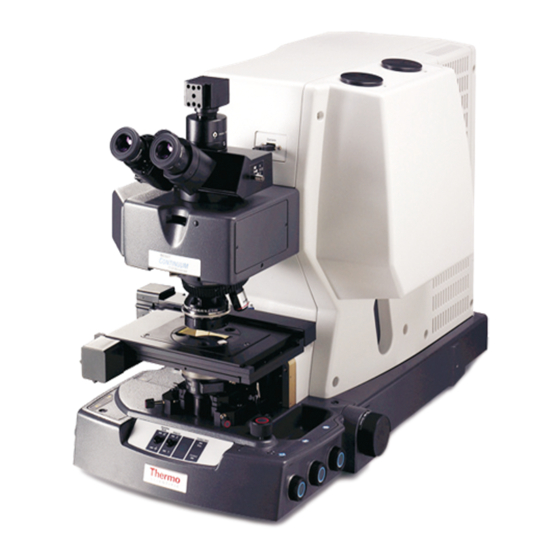
Nicolet Continuµm Microscopes Congratulations on your purchase of a Thermo Scientific Nicolet Continuµm microscope! The Continuµm™ microscope is an infrared microsampling system that provides the highest available IR spatial resolution. The Continuµm design enables unlimited sampling and mapping capability, and incorporates unprecedented ease of use. -
Page 6: Questions And Concerns
If you have questions or concerns about safety or need and concerns assistance with operation, repairs or replacement parts, you can contact our sales or service representative in your area or use the information at the beginning of this document to contact us. Thermo Scientific... -
Page 7: About This Manual
This manual explains how to use the system to collect and process About FT-IR spectra after a Nicolet™ Series spectrometer and Nicolet this manual Continuµm microscope are installed. Included is basic information about using OMNIC Atlµs software, as well as chapters on how to operate the microscope. -
Page 8: Microscope Components
The following illustrations identify the microscope controls and Microscope components. components Thermo Scientific... - Page 9 Front panel Continuµm User Guide...
- Page 10 Control panel (on left side) Thermo Scientific...
-
Page 11: Preparing The Microscope
Preparing the Microscope This chapter explains how to prepare a Continuµm microscope for data collection. It includes information about: • Turning on the power • Cooling the detector • Initializing the microscope stage and, if necessary, limiting stage travel • Preparing the optics Notice The computer and microscope components of your system should... - Page 12 Before you turn on the microscope power, it is a good idea to verify that the illuminator controls are in the OFF position. Rotate the controls counterclockwise until they click into the OFF position. Then move the power switches to the ON position. “I” = On “O” = Off Thermo Scientific...
- Page 13 The power switches are located: • On the control panel on the left side of the microscope. • On the front panel of the optional stage controller. • On the computer, monitor, printer and other peripheral devices. • On the spectrometer power supply. Continuµm User Guide...
- Page 14 Finally, turn on the spectrometer power. To ensure that all the components are recognized, the spectrometer always should be the last component in a microscope system that is powered on. Thermo Scientific...
-
Page 15: Cooling The Detector
The microscope is equipped with one or two single-element Cooling the detector detectors. Most of these detectors must be cooled with liquid nitrogen before use. Caution Liquid nitrogen is extremely cold and can cause injury. A warm laboratory dewar, funnel, and detector may cause the liquid nitrogen to boil rapidly and spatter. - Page 16 The fill ports are offset, toward the front of the access port. To prevent damage to the microscope internal components, be sure that the neck of the funnel is inside the fill port. Damage caused by spilled or misdirected liquid nitrogen is not covered by warranty. Thermo Scientific...
-
Page 17: Installing The Purge Baffle
4. After you have filled the funnel once, allow the detector dewar to cool for one to two minutes before adding more liquid nitrogen. Filling the detector too quickly can cause unnecessary boil off and hazardous splatter. 5. Continue filling the funnel and allowing the nitrogen to drain into detector dewar. -
Page 18: Initializing The Stage
For more information about calibrating the X-Y movement of the stage, find “calibrating stage” in the Atlµs Help system Index and go to “How to calibrate the stage”. Thermo Scientific... -
Page 19: Z-Axis
Whenever the Z-axis of the stage requires initialization, you will see Z-axis the message: when you open the Atlµs window. This message indicates that the system needs to initialize vertical stage movement to allow accurate vertical positioning through the software. Notice Always remove the nosepiece and lower the condenser completely before you initialize the stage. - Page 20 2. Choose System Configuration from the Atlµs menu in OMNIC. 3. Click the Z-Axis button in the Microscope field. Thermo Scientific...
- Page 21 Notice Always remove the nosepiece and lower the condenser completely before initializing the stage. Damage resulting from stage collisions is not covered by warranty. 4. Choose OK when the Stage Initialization information box appears to begin the initialization. Choose Cancel if you do not wish to calibrate the Z-axis at this time.
-
Page 22: Xy-Axes
“Setting up for experiments” Help book available through Microscope Help topics in the OMNIC Help menu, if you are unfamiliar with the procedures for removing and reinstalling the condenser and nosepiece. To initialize the XY-axes: 1. Remove the nose piece and condenser. Thermo Scientific... - Page 23 2. If a universal slide holder is installed, remove it. 3. Choose System Configuration from the Atlµs menu. Continuµm User Guide...
- Page 24 Choose Cancel if you do not wish to calibrate the XY-axes at this time. 6. Wait while the stage initializes. While the stage is being calibrated, no other system configuration parameters can be edited and no other system configuration operations can be conducted. Thermo Scientific...
- Page 25 To prevent accidental initiation of other operations during stage initialization, no other fields are visible and the initialization button is disabled, as shown below. When the initialization is complete, all fields in the System Configuration dialog box become visible again and all controls are reactivated.
-
Page 26: Limiting Stage Travel
Limit Stage Travel dialog. Damage due to stage collision is not covered under warranty. To limit stage travel: 1. Click the Limit Stage Travel button in the Microscope field of the System Configuration dialog box. Thermo Scientific... - Page 27 2. When the Limit Stage Travel dialog box appears, choose the method for entering the travel limits. Choose “Use wizard” if you do not know the limits of stage travel. The Stage Travel Wizard will prompt you to move the stage to the travel limits and record coordinates.
- Page 28 If Use Stage Travel Limits is not selected, the settings are saved, but stage travel is not restricted when you choose OK. You can select this option later to put the settings into effect. This lets you easily limit the stage travel just when you want to. Thermo Scientific...
-
Page 29: Controlling Stage Movement
6. Choose OK to save your setting and close the dialog box. Choose Cancel to close the dialog without saving the limits you entered. For microscopes equipped with the standard manual stage, horizontal Controlling movement of the stage is controlled with the X and Y knobs, located stage movement on the right side of the microscope. - Page 30 To avoid damaging the microscope, be careful not to move the stage up into the objective or down onto the condenser. Stage and/or sample collisions can permanently damage the optical components. Damage caused by stage or sample collisions is not covered under warranty. Thermo Scientific...
- Page 31 The manual control has two speeds: slow for fine focus and fast for coarse focus. Very fine focus controls are in OMNIC Atlµs. To make a fine adjustment, turn the knob just enough to cause movement of the stage. To make a coarse adjustment, turn the knob farther. The harder the knob is turned, the more course the adjustment, the faster the stage movement.
-
Page 32: Preparing The Optical Components
The optical components can be optimized for each user. Use the Preparing the following procedures to prepare the optical system for use. Have optical components each user record their individual settings. Using these settings, the microscope optics can be quickly returned for each individual’s optimum viewing. Thermo Scientific... -
Page 33: Adjusting The Eyepieces
The eyepieces are individually adjustable for focus and viewing Adjusting the eyepieces comfort. The ability to sharply focus on sample features is critical to obtaining good data. 1. Set the view selector for viewing through the eyepieces only. A three-position view selector is located on the side of the microscope, between the camera and the nosepiece. - Page 34 3. Select reflection viewing mode by pressing the Sampling Mode switch on the front panel. The Reflection indicator glows when reflection mode is selected. Note The Sampling Mode switch is not active while Experiment Setup (available through the OMNIC Atlµs Collect menu) is open. Thermo Scientific...
- Page 35 4. Adjust the reflection illumination to high intensity, then adjust the transmission and Reflex aperture illumination to their lowest intensities. Continuµm User Guide...
- Page 36 5. Open both field of view irises completely and then set both aperture irises for low contrast. See “Adjusting field of view and image contrast” in the “More about the Hardware” chapter if you are not familiar with adjusting irises. Thermo Scientific...
- Page 37 6. If you are using a Reflachromat objective and condenser, set the objective and condenser compensation rings to 0. If you are using a fixed objective and condenser, be sure it is rated for 0 refractive index compensation. Continuµm User Guide...
- Page 38 8. Position the pinhole directly under the objective. Look directly at the slide (not through the viewer) and use the stage focus controls to raise or lower the stage until the spot of white light on the slide is most concentrated (the smallest spot size). Thermo Scientific...
- Page 39 Then, while looking directly at the slide, move the stage so that the pinhole is centered on the spot of white light. When you are finished, set the reflection illumination to medium intensity. 9. Adjust the interocular distance on the eye pieces for comfort. You should see a single image of the pinhole through the viewer when the eyepieces are positioned correctly.
-
Page 40: Reticle Focus And Diopter Adjustments
Hold the inner ring with one hand and turn the outer ring until the reticle cross hairs are clear. Once the cross hairs are clear, use the stage focus knob to obtain a sharp image of the pinhole through the right eyepiece. Thermo Scientific... - Page 41 2. Match the focus of the eyepieces. While looking through the left eyepiece with your left eye, turn the eyepiece until the image is in focus. 3. When you are finished, look at the reading on the scale on the outside of the left eyepiece (the white dot indicates the numerical value).
-
Page 42: Condenser Focus And Alignment
To focus the condenser: 1. Use the Sampling Mode button on the front panel to switch the microscope into transmission sampling mode. The transmission indicator lights whenever the microscope is in transmission sampling mode. Thermo Scientific... - Page 43 When you look through the eyepieces, you may notice that the aperture has gone out of focus. Note The Sampling Mode switch is not active while Experiment Setup (available through the OMNIC Atlµs Collect menu) is open. 2. While looking through the eyepieces, use the condenser focus knob to move the condenser up or down to bring the aperture back into sharp focus.
- Page 44 Once the condenser is focused, you can verify that it is centered. The post-sample and pre-sample aperture images should be centered on the same point. To check condenser centering: 1. Open the transmission and reflection field of view controls fully. Thermo Scientific...
- Page 45 2. Turn on Reflex aperture illuminator. Continuµm User Guide...
- Page 46 Each knob moves the condenser diagonally. While their effect is independent, these knobs are usually adjusted simultaneously to center the condenser image. You will find that your adjustment technique improves with practice. Thermo Scientific...
-
Page 47: Initializing The Reflex Aperture
Your microscope may be equipped with an optional automated Initializing the Reflex aperture system. For visual microscopy applications, you can Reflex aperture adjust the aperture manually, using the controls on the right side of the microscope. For all other applications, use the controls in OMNIC Atlµs or µView software to adjust the size, shape and orientation of this aperture. - Page 48 Thermo Scientific...
- Page 49 For systems with automated Reflex apertures, adjustments can be made to the Reflex aperture graphically, using the box shown above, or numerically in the Aperture Dimensions dialog box available through the Atlµs menu. The aperture must be initialized before the first use and any time that the physical aperture and the virtual aperture are out of synch.
- Page 50 When the Atlµs window opens, you will see navigation pane (left side of screen) that shows the current stage location and a video pane (right side of screen). The colored box in the video pane represents the virtual aperture. Thermo Scientific...
- Page 51 3. Adjust the Reflex aperture illumination so that the physically apertured area is brighter than the rest of the field of view. The apertured area is rectangular. Its current size, shape and orientation depend on how the aperture was last adjusted. 4.
- Page 52 When the initialization is finished, the physical and virtual apertures are set to a 100 µm x 100 µm square (50 µm x 50 µm for objectives with greater than 15x magnification) at 0 degrees rotation. Thermo Scientific...
-
Page 53: Analyzing Samples
Analyzing Samples This chapter explains how to use a Nicolet Continuµm microscope and OMNIC Atlµs to collect infrared spectra of samples in reflection and transmission modes. Use the standard experiments and the samples that came with the microscope to perform these experiments and familiarize yourself with the microscope controls and software. - Page 54 If you were analyzing the sample with a fixed-compensation objective, you would use an objective with a refractive index compensation value of 0. 3. Start OMNIC and select “Reflection discrete point – standard sample” from the Experiment drop-down list box. Thermo Scientific...
- Page 55 4. Choose Show Atlµs Window from the Atlµs menu. When the Atlµs window opens you will see the video pane on the right side of the screen, the navigation (stage position) pane on the left, and the Atlµs tool palettes near the bottom of the screen.
- Page 56 Set the reflection illumination to a comfortable viewing level. Notice Use care when focusing images. Be sure that the stage does not bump the objective or condenser. Damage from stage collisions is not covered by warranty. Thermo Scientific...
- Page 57 6. Use the joystick or Move Stage tools to move the sample into the field of view and then use the Z-axis or stage focus knob sharply focus on the ink pattern. You should now be able to see a clear image of the ink in the video pane.
- Page 58 Adjust the reflection aperture iris for good contrast in the video image. Thermo Scientific...
- Page 59 8. If you have an optional motorized stage, home the stage to the area of interest in your sample. Choose Move Stage from the Atlµs menu and then choose Set Home to Current. 9. Refine the standard experiment background and sample point area settings for your sample position.
- Page 60 Click the Background Point tool. Choose an ink-free point near the center of the video pane and click. Atlµs moves the background point to the new point you chose. 10. Center the sample point of interest in the field of view. Thermo Scientific...
- Page 61 11. If necessary make final adjustments to the Reflex aperture to mask an area of interest on the sample. For automated apertures, use the arrow tool to grab a handle on any side of the virtual aperture to drag the aperture to the size and shape preferred for your ink spot.
- Page 62 Background handling Background before every sample Collect 64 scans for background Bench tab Sample Compartment Left µscope %R Right µscope %R Detector your single-element detector (Usually MCT-A) Beamsplitter your compatible beamsplitter (usually KBr) Source Accessory None Window None continued… Thermo Scientific...
- Page 63 Where Parameter Setting Bench tab, continued… Max range limit 4000 Min range limit Gain Autogain Velocity 1.8988 Aperture Advanced tab Zero filling none Apodization Happ-Genzel Phase correction Mertz Set sample spacing based on spectral range Set filters based on velocity Single-sided interferogram Reset bench at...
- Page 64 Save video frames in map file Prompt before collecting data All others Rectangular None Mapping focus Do not focus during options map collection When you are finished, choose OK to save the settings and return to the Atlµs window. Thermo Scientific...
- Page 65 13. Choose Collect Map from the Collect menu. Observe as the video mosaic is collected. 14. When the software prompts, check, if necessary, adjust the position of your background point, and then choose OK. Continuµm User Guide...
- Page 66 15. When the software prompts, check and adjust the sample point location and focus and then choose OK. Respond to any other prompts and then observe as the sample data is collected. 16. When data collection is finished, use the viewer pane to isolate areas of interest. Thermo Scientific...
-
Page 67: Performing A Transmission Experiment
A standard transmission experiment sample was shipped in the Performing a accessory box. This sample can be used to perform your first transmission transmission discrete point experiment and whenever you wish to experiment confirm that your microscope is operating properly. Before you begin, be sure that the condenser is centered and focused. - Page 68 If you were analyzing the sample with a fixed-compensation objective and condenser, you would use an objective and condenser with a refractive index compensation value of 0. Thermo Scientific...
- Page 69 4. Start OMNIC and select “Transmission discrete point – standard sample“ from the Experiment drop-down list box. 5. Choose Show Atlµs Window from the Atlµs menu. When the Atlµs window opens you will see the video pane on the right side of the screen, the navigation (stage position) pane on the left, and the Atlµs tool palettes near the bottom of the screen.
- Page 70 Set the reflection illumination to a comfortable viewing level. Notice Use care when focusing images. Be sure that the stage does not bump the objective or condenser. Damage from stage collisions is not covered by warranty. Thermo Scientific...
- Page 71 7. Use the joystick to move the sample into the field of view and then sharply focus on the XL pattern. You should now be able to see a clear image of the ink in the video pane. Note A yellow circle in the Bench Status field usually indicates that the detector has not been cooled.
- Page 72 Adjust the transmission and reflection aperture irises for good contrast in the video image. Thermo Scientific...
- Page 73 9. If you have an optional motorized stage, home the stage the area of interest in your sample. Select Move Stage from the Atlµs menu and then choose Set Home to Current. This allows you to easily return to your data sampling point.
- Page 74 Click the Background Point tool. Choose a point near the center of the video pane and click. Atlµs moves the background point to the point you select. Thermo Scientific...
- Page 75 11. Center the sample point of interest in the field of view. 12. If necessary, make final adjustments to the Reflex aperture to mask an area of interest on the sample. For systems equipped with an automated Reflex aperture, use the arrow tool to grab a handle on any side of the virtual aperture to drag the aperture to the size and shape preferred for your ink spot.
- Page 76 Sample Compartment Left µscope %T Right µscope %T Detector your single-element detector (Usually MCT-A) Beamsplitter your compatible beamsplitter (usually KBr) Source Accessory None Window None Bench tab Sample Compartment Left (or right, depending on your setup) µScope, %T Thermo Scientific...
- Page 77 Where Parameter Setting Bench tab, continued… Detector your single element detector (Usually MCT-A) Beamsplitter Source Accessory None Window None Max range limit 4000 Min range limit Gain Autogain Velocity 1.8988 Aperture Advanced tab Zero filling none Apodization Happ-Genzel Phase correction Mertz Set sample spacing based on spectral range...
- Page 78 Mapping focus options Do not focus during map collection When you are finished, choose OK to save the settings and return to the Atlµs window. 14. Choose Collect map from the Collect menu. Observe as the video mosaic is collected. Thermo Scientific...
- Page 79 15. When the software prompts, check the position of your background point (adjust if necessary) and then choose OK. Observe as the background is collected. If prompted to save the background, choose Yes. 16. When the software prompts, check and, if necessary, adjust the sample point.
- Page 80 17. When data collection finishes, use the viewer pane to isolate peaks of interest. Thermo Scientific...
-
Page 81: Advanced Techniques
Advanced Techniques This chapter describes the following optional, advanced techniques that you can perform with a Continuµm microscope: • Polarization • Attenuated total reflection • Grazing angle reflection The Continuµm microscope can be equipped with optional Polarization options polarizers that polarize visible or infrared beams. Visible polarization is used to generate contrast in aniso ropic materials. - Page 82 2. Insert the round visible polarizer into either of the color filter ports. If your sample is suited for transmission data collection, insert the polarizer in the transmission color filter port. The transmission color filter port is located on the base of the microscope on the left side. Thermo Scientific...
- Page 83 If your sample is suited for reflection data collection, insert the polarizer into the reflection color filter port. The reflection color filter port is located on the left side of the microscope, adjacent to the reflection illuminator. 3. Select a sampling mode. Check to be sure that Experiment Setup (available through the Collect menu of OMNIC Atlµs) is closed and then use the Sampling Mode switch on the front panel.
- Page 84 The optional rotatable stage is ideal for this type of experiment. The universal slide holder can also be rotated. We recommend that you rotate the sample rather than the polarizer while looking for differences in sample composition. Thermo Scientific...
-
Page 85: Nomarski Differential Interference Contrast
7. Use the X-Y knobs, joystick or Move stage tools to center the features of interest in the field of view. 8. Adjust the Reflex aperture to mask the area of interest on the sample. 9. Prepare to take data as you normally would for a typical infrared transmission or reflection experiment. - Page 86 Follow these steps to perform DIC experiments: 1. Remove the purge baffle and then slide the visible analyzer into the slot directly below the viewer. Thermo Scientific...
- Page 87 2. Insert the round visible polarizer into one of the color filter ports. If your sample is suited for transmission data collection, insert the polarizer in the transmission color filter port. The transmission color filter port is located on the base of the microscope on the left side.
- Page 88 Collect menu of OMNIC Atlµs) is closed and then use the Sampling Mode switch on the front panel. If your sample is suited to reflection techniques, choose reflection mode. If your sample is suited to transmission techniques, choose transmission mode. Thermo Scientific...
- Page 89 The Transmission indicator lights when transmission mode is selected. The Reflection indicator lights when reflection mode is selected. 4. Rotate the round visible polarizer with your finger until the field of view becomes dark. The polarizers are now crossed. Note Some video cameras include autogain features that make it difficult to see when the polarizers are crossed.
- Page 90 5. Loosen the thumbscrew and remove the purge baffle from the nosepiece. 6. Insert a DIC prism (with the lettering facing up) into the nosepiece slot. Thermo Scientific...
- Page 91 7. If your sample is suited to transmission data collection, remove the purge baffle from the condenser. If your sample is suited to reflection data collection, proceed to step 9. Continuµm User Guide...
- Page 92 8. If your sample is suited to transmission data collection, insert a DIC prism (with the lettering facing down) into the condenser slot. 9. Install the sample and focus. 10. Rotate the DIC prism knob(s) to change the colors and contrast of the sample image. Thermo Scientific...
-
Page 93: Infrared Polarization
Note You can usually obtain the greatest contrast by rotating the knobs until the image is black and white (without visible color). If you are interested in obtaining information that is specific to Infrared polarization sample orientation, that gives precise information about the molecular structure and molecular orientation of a sample, or that is specific to polarization angle you can use the microscope to conduct polarized studies of infrared data. -
Page 94: Optical Filters
The purge baffles located in the objective and the condenser can be Optical filters used as holders for custom filters. Round filters ranging in diameter from 29 to 36 mm with a maximum thickness of 3.5 mm. The magnetic pads can be used to secure filters. Thermo Scientific... -
Page 95: Attenuated Total Reflection
An optional ATR (attenuated total reflection) objective and slide-on Attenuated ATR attachment lets you analyze highly infrared-absorbent or hard- total reflection to-prepare microscopic materials, often with little or no sample preparation. Examples of these materials include polymers, coatings, rubbers, coated papers and biological materials. Applications of ATR microscopy include: •... -
Page 96: Setting Up The Internal Contact Alert System
Caution Avoid shock hazard. Before connecting the sensor plate, always turn off the microscope power. 1. Turn off the microscope, computer, spectrometer, and stage controller power. Thermo Scientific... - Page 97 2. Lower the condenser completely. Use the condenser focus knob. Continuµm User Guide...
- Page 98 3. If the universal slide holder is in place, remove it from the stage. Thermo Scientific...
- Page 99 4. Connect the cable from the sensor plate to the connector on the front of the microscope and set the sensor plate aside. To prevent damage when the stage initializes, be sure that the cable that connects the sensor plate to the microscope is behind and under the stage.
- Page 100 See “Initializing the stage” in the “Preparing the Microscope” chapter, if you are unfamiliar with the stage initialization procedures. 7. Place the sensor plate onto the stage. The raised surface on the bottom of the sensor plate fits into the recess on the stage. Thermo Scientific...
- Page 101 Be sure that the cable that connects the sensor plate to the microscope is on top of the stage. 8. Choose System Configuration from the Atlµs menu in OMNIC. 9. Click the Configuration button under Initialization in the Microscope field. Continuµm User Guide...
- Page 102 If Auto ATR is checked, click the Close button to close the dialog box without changes. If it is not, check the box, click the Save button, and then click the Close button to enable Auto ATR and close the dialog box. Thermo Scientific...
- Page 103 11. Once you return to the System Configuration dialog box, click OK to save the Auto ATR setting and close the dialog box. Click the ATR Calibration button in the Video field. See the OMNIC Atlµs Help system for more information about ATR calibration.
-
Page 104: Using The Internal Contact Alert System
1. Select reflection viewing mode. Check to be sure that Experiment Setup (available through the Collect menu of OMNIC Atlµs) is closed and then use the Sampling Mode switch on the front panel. Thermo Scientific... - Page 105 2. Firmly grip the nosepiece ring and rotate the ATR objective or the standard infrared objective with the slide-on ATR attachment into the viewing-analyzing position. 3. Select a “view through” position for the objective. If you are using an ATR objective with a ZnSe or diamond crystal, slide the selector into the survey position.
- Page 106 The glass will crack before the objective is damaged. Applying transparent tape to the underside of the glass slide will prevent pieces from falling into the condenser should the slide break. Thermo Scientific...
- Page 107 You can insert a round window made of KBr or other appropriate material into one of the holes in the metal slide that came with your system and then place the sample on that window. If you choose to use the metal slide, be very careful when you apply pressure.
- Page 108 If you are using an ATR objective with a Ge or Si crystal, look directly at the sample from the side and position it as desired under the objective. Thermo Scientific...
- Page 109 9. Move the crystal into the beam path. If you are using an ATR objective with a ZnSe or diamond crystal type, slide the selector into the ATR position. If you are using the slide-on ATR attachment, move the crystal slide to the middle position.
- Page 110 10. 13. Choose Experiment Setup from the Collect menu, and verify that the detector signal intensity is adequate. The detector signal is shown in the live display on the Bench tab of the Experiment Setup dialog box. Thermo Scientific...
- Page 111 If you need help, find “live display’ in the OMNIC Help system Index and go to “Using the live display.” 14. Set Background Handling on the Collect tab to collect Background After Every Sample. Set the other experiment parameters to the appropriate settings. (If you have set up and saved an experiment for ATR data collection, you can set the parameters in one step by opening the experiment.)
-
Page 112: Setting Up The External Quantitative Contact Alert System
Contact Alert system. Use this option when you need to measure samples with the best possible reproducibility of contact pressure; for example, for quantitative analyses or research studies. Caution Avoid shock hazard. Before connecting the quantitative Contact Alert System, always turn off the microscope power. Thermo Scientific... - Page 113 To set up the external Contact Alert System: 1. Turn off the microscope, computer, spectrometer, and stage controller (if installed) power. Continuµm User Guide...
- Page 114 2. Lower the condenser fully. Use the condenser focus knob. Thermo Scientific...
- Page 115 3. If the universal slide holder is in place, remove it from the stage. Continuµm User Guide...
- Page 116 Be sure that at least 20 seconds elapses between powering on the microscope and powering on the spectrometer. See “Turning on power” in the “Preparing the Microscope” chapter, if you need help with powering on the system. Thermo Scientific...
- Page 117 6. Initialize the stage. See “Initializing the stage” in the “Preparing the Microscope” chapter, if you are unfamiliar with the stage initialization procedures. 7. Place the sensor plate onto the stage. The raised surface on the bottom of the sensor plate fits into the recess on the stage.
- Page 118 If Auto ATR is not checked, click the Close button to close the dialog box without changes. If it is, click the checkbox to uncheck it, click the Save button, and then click the Close button to disable Auto ATR and close the dialog box. Thermo Scientific...
- Page 119 11. Once you return to the System Configuration dialog box, click OK to save the Auto ATR setting and close the dialog box. 12. Click the Video Calibration button in the Video field. See the OMNIC Atlµs Help system for more information about ATR calibration.
-
Page 120: Grazing Angle Reflection
Make sure the GAO is properly installed and aligned on the microscope. Notice Before rotating the GAO into position, lower the stage to provide sufficient clearance between the stage and the objective. The working distance of the GAO when focused on the sample is 1 mm. Thermo Scientific... - Page 121 1. Select reflection sampling mode. Check to be sure that Experiment Setup (available through the Collect menu of OMNIC Atlµs) is closed and then use the Sampling Mode switch on the front panel. 2. Install the sample on an appropriate reflective substrate on a sample slide and place it on the microscope stage.
- Page 122 4. Using the stage focus knob, slowly raise the stage so that the sample is approximately 2 mm from the bottom of the GAO. 5. Slide the GAO mode selector to “View”. Thermo Scientific...
- Page 123 6. Using the Z position tool, slowly raise the stage so that the sample is approximately 1 mm from the bottom of the GAO. Check the Fast checkbox if you have difficulty controlling the stage using the very fine adjustment mode. 7.
- Page 124 GAO a clean area of the reflective substrate on which the sample is installed. Do not adjust the Reflex aperture or the GAO. 14. While looking through the viewer (or at the video image), finely focus the image of the substrate surface. Thermo Scientific...
- Page 125 15. Choose OK to collect the background spectrum (spectrum of the substrate). 16. When data collection is finished, follow the instructions that appear on the screen to display the ratioed sample spectrum in a spectral window. If Collect To a New Window is turned on in the Collect options, the spectrum is displayed in a new spectral window automatically.
- Page 126 Thermo Scientific...
-
Page 127: More About The Hardware
More about the Hardware This chapter provides more information about components of the Continuµm microscope. We will cover these topics: • Selecting a detector • Using objectives and condensers • Masking off areas of interest • Adjusting contrast and the field of view •... - Page 128 Note Before you can collect data using either the array or a single element detector, you will need to cool it. See “Cooling the detector” in the “Preparing the Microscope” chapter for instructions for cooling a detector. Thermo Scientific...
- Page 129 Also, be sure that the beamsplitter and source installed in your spectrometer are compatible with the microscope detector you have selected. The table that follows lists the beamsplitter-detector combinations that can be used. Beamsplitter Near-IR Mid-IR* Far-IR Solid Detector Quartz XT-KBr substrate MCT-A*...
- Page 130 The range achieved using one of these sources will not be as broad as the total range shown. These detectors must be cooled with liquid nitrogen before use. CsI beamsplitters are extremely hygroscopic (sensitive to moisture). Thermo Scientific...
-
Page 131: Using Objectives And Condensers
A wide variety of objectives and condensers are available from us. Using objectives Each nosepiece may have 1–4 objectives installed. With the and condensers nosepiece installed, it is a simple matter to move a particular objective into the beam path. Notice To prevent damage to the internal mirror, avoid inserting your finger or any other object through the opening on the underside of an... -
Page 132: Specifications And Typical Uses
The table that follows lists many of the objectives that are available Specifications for use with a Continuµm microscope. It includes a summary of their and typical uses specifications, and typical uses. For transmission applications, choose a condenser that matches magnification of the objective you are using. Thermo Scientific... - Page 133 Objective Specifications Used for Glass Wide variety ranging from 4X to 50X Visual microscopy and as an aid in sample magnifications alignment. Useful for adjusting image contrast for video and photomicrography or to aid in measuring optical properties such as refractive index, angle of extinction, birefringence, and signs of elongation 15X Cassegrain...
-
Page 134: Refractive Index Compensation
If the sample is installed on a substrate, the condenser compensation value should match the substrate thickness. If a window is placed on top of the sample, the objective compensation value should match the window thickness. Thermo Scientific... - Page 135 To adjust the compensation of a Reflachromat objective, firmly Adjusting grasp the black finger cap and rotate the knurled, silver ring so that objective compensation the number corresponding to the sample substrate thickness is aligned with the vertical, white line. To adjust he compensation of the Reflachromat condenser, rotate the Adjusting wide, knurled, silver ring so that the indicator is aligned with the...
-
Page 136: Adjusting Field Of View And Image Contrast
The transmission and reflection illuminators each have a set of irises Adjusting that control the field of view and image contrast. The controls for the field of view irises are located adjacent to the illuminator bulbs they serve. and image contrast Thermo Scientific... -
Page 137: Transmission Irises
The transmission illuminator has two circular irises that control the Transmission irises size of the illuminated field of view and the image contrast for transmission experiments. Field iris – Use the field iris to adjust the size of the illuminated field of view. -
Page 138: Masking Off Areas Of Interest
It also ensures that the small amount of diffracted radiation that passes around the edges of the sample area of interest does not reach the detector. Thermo Scientific... -
Page 139: Adjusting The Aperture Size, Shape And Orientation
The microscope’s optical design is symmetrical with respect to the sample and aperture. This lets you use a single aperture for masking both before and after the sample. Also, the pre-and post-sample aperture size and orientation are identical. The pre-sample aperture position is fixed in relation to the objective in both transmission mode and reflection mode. -
Page 140: Using The Software To Adjust The Aperture
If the post-sample aperture image is not perfectly aligned with the box when the microscope is in transmission mode, use the condenser centering knobs to align it. See “Condenser focus and alignment” in the “Preparing your microscope” chapter for more information. Thermo Scientific... - Page 141 1. Choose Aperture Dimensions from the Atlµs menu. The Aperture dialog box appears. Note The settings in this dialog box are not linked to those in the dialog box displayed by the Aperture button on the Mapping tab of the Experiment Setup dialog box.
-
Page 142: Using The Manual Controls To Adjust The Aperture
This is useful for setting the aperture size to adjust the aperture while viewing the sample through the eye pieces. Use the knobs on the right-side of the microscope to manually adjust the aperture. Thermo Scientific... - Page 143 Manual changes to the aperture size, shape, or orientation are not tracked by the automated aperture software. If the aperture is set in software, software will attempt to return the aperture to the size, shape, and orientation set in the experiment parameter prior to data collection.
- Page 144 The front knob controls the orientation of the aperture. Turn the knob clockwise to rotate the aperture clockwise; turn the knob counterclockwise to rotate the aperture counterclockwise. You can rotate the aperture a maximum of 45 degrees in either direction. Thermo Scientific...
-
Page 145: Using Autofocus
If your system is equipped with an optional autofocus package, you Using autofocus can use the OMNIC Atlµs or µView software to focus the microscope automatically when a sample is centered in the field of view. Follow the steps below to perform an experiment using autofocus. For complete information on using the software features, see the documentation that came with the software. - Page 146 2. Place the sample on the stage and position it within the field of view. 3. Increase the reflection illumination so that it is brighter than normal viewing intensity. Thermo Scientific...
- Page 147 4. While viewing the sample from the side (not through the eyepieces), use the stage focus knob to raise or lower the stage to focus the dot of white light hitting the sample plane. You may need to increase the reflection illumination further to see the dot clearly.
- Page 148 You must be within 1 mm of focus for autofocus to succeed. 7. Center the sample area of interest in the field of view and adjust the aperture. 8. Start the experiment. Thermo Scientific...
-
Page 149: Using Auto Atr Contact
If you have the auto ATR contact option and are using the Contact Using auto Alert circuitry that was built into the microscope, you can use the ATR contact OMNIC Atlµs software to make sample contact automatically. Follow the steps below to perform an ATR experiment using auto ATR contact. - Page 150 3. Select a refractive (glass) objective or a 15X or 32X Reflachromat objective. 4. Place the sample on the stage and position it within the field of view. Thermo Scientific...
- Page 151 5. Increase the reflection illumination so that it is brighter than normal viewing intensity. Continuµm User Guide...
- Page 152 8. While viewing the video image of the sample or looking through the eyepieces, center and finely focus the sample image. 9. Adjust the Reflex aperture. Only the portion of the sample to be analyzed should be illuminated. Thermo Scientific...
- Page 153 10. Select the ATR objective or the 15X Reflachromat objective with the slide-on ATR attachment. 11. If you are using an ATR objective, slide the selector into the ATR position. If you are using the slide-on ATR attachment, move the crystal slide to the middle position. 12.
- Page 154 Thermo Scientific...
-
Page 155: Troubleshooting
Troubleshooting This chapter provides information about symptoms and possible solutions for problems you might encounter while using the microscope. It also provides information about how to check the microscope performance. The following table describes some problems that could occur when Symptoms you use the microscope and explains how to solve them. - Page 156 When you are finished, run the Noise Test in transmission modes See “Testing microscope performance” later in this chapter if you need help. If the image cannot be brought into sharp focus, performance has dropped off, or the Noise Test fails, contact technical support. continued… Thermo Scientific...
- Page 157 Symptom Possible Cause Solution No signal appears in the The spectrometer is powered Verify that the spectrometer power is ON Bench tab live display OFF. and that the power supply and power cord available through Experiment are firmly seated and connected to an AC Setup, continued…...
- Page 158 The sample is out of focus. Atlµs or µView window is tools and bring the sample into focus. dark grey or black. Remove the sample, focus and center the condenser, re-install the sample and then attempt to bring it into focus. continued… Thermo Scientific...
- Page 159 Symptom Possible Cause Solution Adjust the field and aperture iris settings. See Video pane of the OMNIC Field of view and/or contrast Atlµs or µView window is controls are improperly “Adjusting field of view and contrast” in the dark grey or black, adjusted.
- Page 160 Microscope” chapter. The power source or power Verify that the power cords are connected to cord is damaged. a working AC source (wall outlet or power strip) and firmly seated at both ends. Replace any damaged cables. continued… Thermo Scientific...
- Page 161 Symptom Possible Cause Solution Video pane of the OMNIC Video signal is not reaching the Verify that a video cable (composite or S Atlµs or µView window is a computer. Video) is connected between the computer solid blue color, continued… and to the microscope control panel.
- Page 162 Noise Test fails, contact technical support. One or more illuminators are Make sure illuminators are turned on and turned off or not adjusted adjusted properly. See “Preparing the optical properly. components” in the “Preparing the Microscope” chapter. continued… Thermo Scientific...
- Page 163 Symptom Possible Cause Solution No image appears in the video One or more illuminator bulbs Verify that bulbs are still functioning by pane or the viewer, are burned out. adjusting illumination to maximum intensity continued... and looking for light inside bulb access covers.
- Page 164 When you are finished, run the Noise Test in transmission modes See “Testing microscope performance” later in this chapter if you need help. If the image cannot be brought into sharp focus, performance has dropped off, or the Noise Test fails, contact technical support. continued… Thermo Scientific...
- Page 165 Symptom Possible Cause Solution Signal is weak without a Stage bumped the condenser or Center and focus the condenser and focus the sample in beam path, objective objective. See “Preparing the optics” in the continued… “Preparing the Microscope” chapter. When you are finished, run the Noise Test in transmission and reflection modes.
- Page 166 See “Testing microscope performance” later in this chapter if you need help. If the image cannot be brought into sharp focus, performance has dropped off, or the Noise Test fails, contact technical support. continued… Thermo Scientific...
- Page 167 Symptom Possible Cause Solution The condenser is out of focus Center and focus the condenser and focus the and/or off center. objective. See “Preparing the optics” in the “Preparing the Microscope” chapter. When you are finished, run the Noise Test in transmission modes See “Testing microscope performance”...
- Page 168 Quantitative Contact Alert, if installed Computer Spectrometer The stage controller cannot Verify that the communications cable is communicate with the firmly seated. computer. The stage and/or stage Replace the fast mapping stage, controller is malfunctioning Contact technical support. continued… Thermo Scientific...
- Page 169 Symptom Possible Cause Solution The optional fast mapping The stage calibration Enter the correct compensation numbers. A stage moves erratically. parameters are not correct. label on the bottom of the stage provides the correct compensation numbers for your stage. Find “stage” in the OMNIC Atlµs Help system Index and go to “Calibrating the stage”...
- Page 170 Verify that the stage controller power cord is connected to an AC source (working wall outlet or power strip). Verify that the cable that connects the stage controller to the fast mapping stage is connected. Replace any damaged cables or cords. continued… Thermo Scientific...
- Page 171 Symptom Possible Cause Solution When the Atlµs window is Serial communications Verify that the microscope and the stage open, OMNIC does not problem. controller are powered on. respond but the Windows Verify that the microscope and stage Task Manager does not list controller are connected to an AC source (a OMNIC as “Not working wall outlet or power strip).
-
Page 172: Testing Microscope Performance
1. Open the Atlµs window and initialize the Reflex aperture. This gives an aperture size of 100 by 100 µm if you are using the 15X objective, or a size of 46.875 by 46.875 µm if you are using the 32X objective. Thermo Scientific... - Page 173 When you are finished, the image should look like this: See the section entitled “Initializing the Reflex aperture” in the “Preparing the Microscope” chapter, if you need help. 2. Install the pinhole slide on the stage and use the joystick or software stage controls to position the gold mirror directly under the infrared objective.
- Page 174 3. Adjust the reflection illumination and Reflex aperture illumination to a comfortable viewing level. Thermo Scientific...
- Page 175 4. Use the stage focus knob to obtain a sharp image of the mirror surface. If you find it difficult to focus the image, move the stage to position the edge of the mirror under the objective and focus on the edge.
- Page 176 5. Choose Experiment Setup from the Collect menu. The Experiment Setup dialog box appears. Thermo Scientific...
- Page 177 6. Set the following experiment parameters: Where Parameter Setting Collect tab Number of scans Resolution Final format % Reflectance Correction None Background before Background handling every sample Collect 32 scans for background Left µscope %R Bench tab Sample Compartment Right µscope %R your single element Detector detector...
- Page 178 Advanced tab Zero filling none Apodization Triangular Phase correction Mertz Set sample spacing based on spectral range Set filters based on velocity Single-sided interferogram Reset bench at start of collection Start collection with external trigger Blanking regions None continued… Thermo Scientific...
- Page 179 Where Parameter Setting Quality tab Diagnostic tab Configure tab As you prefer Mapping tab Dimensions Collect type: Discrete points Background Background point is defined Profile type Chemigram Advanced mapping options Save video frames in map file Prompt before collecting data All others Rectangular None...
-
Page 180: In Transmission Mode
1. Open the Atlµs window and initialize the Reflex aperture. This gives an aperture size of 100 by 100 µm if you are using the 15X objective, or a size of 46.875 by 46.875 µm if you are using the 32X objective. Thermo Scientific... - Page 181 When you are finished, the image should look like this: See the section entitled “Initializing the Reflex aperture” in the “Preparing the Microscope” chapter, if you need help. 2. Install the pinhole slide on the stage and use the joystick or software stage controls to position the large open hole directly under the infrared objective.
- Page 182 3. Adjust the transmission illumination to a comfortable viewing level. 4. Focus and then center the condenser image. See “Condenser focus and alignment” in the “Preparing the Microscope” chapter if you need help. Thermo Scientific...
- Page 183 5. Choose Experiment Setup from the Collect menu. The Experiment Setup dialog box appears. Continuµm User Guide...
- Page 184 Accessory None Window None Max range limit 2600 Min range limit 2500 Notes: 1. For InGaAs detectors set the Max range limit to 12000 cm 2. For InGaAs detectors, set the Min range limit to 3800 cm continued… Thermo Scientific...
- Page 185 Where Parameter Setting Bench tab, continued… Gain Autogain Velocity 1.8988 Aperture Advanced tab Zero filling none Apodization Triangular Phase correction Mertz Set sample spacing based on spectral range Set filters based on velocity Single-sided interferogram Reset bench at start of collection Start collection with external trigger...
- Page 186 Mapping focus options Do not focus during map collection If you need help setting the parameters, find “experiment” in the OMNIC Help system Index and go to “Using Experiment Setup.” 7. Choose OK to close the Experiment Setup dialog box. Thermo Scientific...
- Page 187 8. Choose Collect Sample from the Collect menu to collect a sample spectrum. Follow the instructions that appear on the screen. 9. When you are prompted to collect the background spectrum, choose OK. 10. When data collection is finished, follow the instructions that appear on the screen to display the ratioed sample spectrum in a spectral window.
-
Page 188: Upgrading The Computer, Recovering From Viral Attacks, And Reinstalling Software
USB 2.0 serial port If you are unfamiliar with the procedures for adding and removing cards from your computer, see the documentation that accompanied the computer. 3. Power on the computer and, if necessary, install the operating system. Thermo Scientific... - Page 189 4. Install OMNIC Atlµs. Notice For many video capture (and other add-on cards) the drivers and software must be installed before the hardware. Read and follow the installation instructions that accompany the card(s). Incorrectly installed software, hardware, and drivers can render your computer inoperable.
- Page 190 (video capture, serial port, and USB 2.0 port) have been recognized by the operating system and are working properly. 12. Shut down and power off the computer and then, if you are using a Magna-IR or Nexus spectrometer, install the spectrometer interface card. Thermo Scientific...
-
Page 191: Index
Index accessories, 123 collecting aperture ATR spectra, 91 adjusting manually, 133, 138 background spectrum with grazing angle objective, adjusting size of, 133 adjusting with software, 43, 136 spectra and maps, 49 centering image of, 135 spectra with grazing angle objective, 116 condenser centered on image of, 40 compensation for refractive index, 130 focusing image of, 135... - Page 192 5 injury prevention, 2 focal displacement, 130 installing software, 184 focus interocular adjustments, 35 course and fine controls, 35 iris knob, 4 aperture, 133 focusing, 26 field, 133 condenser, 39 illuminator, 32, 133 Reflex aperture image, 135 Thermo Scientific...
- Page 193 language translations, 2 pinhole slide, 34 Limit Stage Travel, 22 polarizing liquid nitrogen, 11 infrared light, 89 visible light, 77 power switch positions, 8 turning on or off, 8, 9 mapping, 8 prism, 81 MCT-A detector purge, 13 noise level, 176, 183 purge baffle, 4 microscope components, 4...
- Page 194 56 location, 4, 5 stage using to choose viewing mode, 29 collision damage, 15, 22 visible analyzer, 77, 82 controller power, 164 visible light polarization, 77 defining home position, 55 does not move, 164 focus knob, 26 Thermo Scientific...
- Page 195 wire-grid infrared polarizer, 89 Z-axis calibrating, 15 course and fine control, 35 zoom controlling with software, 55 XY-axes scale extreme, 164 calibration, 18 initializing, 18 Continuµm User Guide...
Need help?
Do you have a question about the Nicolet Continuum and is the answer not in the manual?
Questions and answers
What is the actual beam size?