Mecademic MECA500 User Manual
Hide thumbs
Also See for MECA500:
- User manual (66 pages) ,
- User manual (42 pages) ,
- User manual (40 pages)

Related Manuals for Mecademic MECA500


Summary of Contents for Mecademic MECA500
- Page 1 MECA500 USER MANUAL For Firmware Version 9.1.x Document Revision: 1 August 31, 2022...
- Page 2 The information contained herein is the property of Mecademic and shall not be reproduced in whole or in part without prior written approval of Mecademic. The information herein is subject to change without notice and should not be construed as a commitment by Mecademic.
-
Page 3: Table Of Contents
Removing power ..............................21 6.3. Offline mode ...............................22 6.3.1 Saving the program via the web interface ......................22 6.3.2 Running an offline program ..........................22 6.4. Robot control panel ............................22 6.4.1 LEDs ..................................23 User manual for Meca500 (for firmware 9.1.x) - Page 4 Buttons ................................... 23 7. OPERATING THE INTELLIGENT POWER SUPPLY ..................25 7.1. LEDs ................................25 7.2. External connections ..........................26 8. INSTALLING AN END-EFFECTOR .........................30 9. EXAMPLES ..............................31 9.1. Draw a square .............................31 10. TROUBLESHOOTING ............................32 User manual for Meca500 (for firmware 9.1.x)
- Page 5 Programming Manual. This manual will guide you through the steps required for setting up your Meca500 and for using it in a safe manner. You must read this user manual thoroughly during the unpacking and first use of your Meca500.
-
Page 7: Introduction
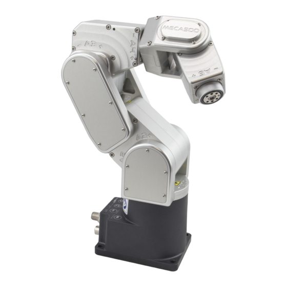
INTROdUCTION 1. INTROdUCTION The Meca500 is a six-axis industrial robot arm that is easy to use, robust and lightweight. However, the robot is a precision device with rapidly moving parts and should therefore be used only by technical personnel who have read and understood this user manual, to avoid damages to the robot, its end- effector, the workpiece and adjacent equipment, and, most importantly, avoid injuries. -
Page 8: Safety
SAfETy 2. SAfETy The Meca500 weighs less than 5 kg, however, it can move fast and cause injuries, especially when certain end-effectors are attached to its flange (e.g., a sharp tool or a laser). The robot also has pinch points where robot joints can squeeze a finger (Figure 1). -
Page 9: Power Supply And Safety Features
The new Mecademic power supply integrates several safety features. Use only the intelligent power supply provided by Mecademic to power your Meca500 robot arm: it will not function with our older power supplies, or other third party 24 V DC power supplies. -
Page 10: Disabling The Robot Brakes
Before leaving the robot deactivated or powered of for more than an hour, bring it to a position that minimizes the static torques on joints 1, 2 and 3. User manual for Meca500 (for firmware 9.1.x) -
Page 11: Technical Specifications
3. TECHNICAL SPECIfICATIONS Table 2 lists the main technical specifications of the Meca500 robot arm. Note that the maximum tool- center point (TCP) speed is software limited to 1,000 mm/s when the robot executes Cartesian-space motion commands, regardless of the definition of the TCP with respect to the robot’s flange. However, if the robot is fully stretched and all joints move at maximum speed, due to a joint-space command, the TCP speed can surpass 2,000 mm/s. - Page 12 TECHNICAL SPECIfICATIONS Figure 4 shows all the link lengths and offsets of the Meca500, necessary for obtaining the so-called Denavit-Hartenberg parameters. Note that all joints are at zero degrees in the configuration drawn in black line. Also note that the gray zone is the area attainable by the center of the robot’s wrist (the intersection point of the last three axes), for a fixed angle of joint 1.
-
Page 13: Installing The Meca500
4. INSTALLINg THE MECA500 You are surely eager to start using your Meca500. It is, however, imperative that you fix solidly the base of your robot arm with four M6 screws before activating the robot. We typically use metric breadboards... - Page 14 1. Attach the circular connector of the Ethernet cable to the ETHERNET1 port on the robot’s base and connect the RJ-45 jack to your computer or router (Figure 6). The two Ethernet ports on the robot’s base act as a bridge, so you can daisy-chain several Meca500 robots, or connect an Ethernet I/O module on the ETHERNET2 port.
- Page 15 Static to force a specific IP. You don’t need to reboot the robot; the new configuration will be applied as soon as you click on the Save button (Figure 10). Figure 9: Options dropdown menu User manual for Meca500 (for firmware 9.1.x)
- Page 16 INSTALLINg THE MECA500 (a) DHCP (b) Static Figure 10: Two ways to change the robot’s network configuration User manual for Meca500 (for firmware 9.1.x)
-
Page 17: The Web Interface
THE wEB INTERfACE 5. THE wEB INTERfACE Meca500’s web interface is more or less the equivalent of the teach pendant’s interface of a traditional industrial robot. The interface is essentially an HTML 5 web page with JavaScript and WebGL scripts. All of these files reside in the robot’s controller, so you do not need to install anything on your computer,... -
Page 18: The Programming Panel
Finally, whenever you have a motion error, the checkbox will become selected and red. To reset the error, you will need to clear the checkbox (or press the below the Program field, as we will explain later). User manual for Meca500 (for firmware 9.1.x) -
Page 19: The Program Editor Field
SetConf and SetConfTurn, with the current inverse kinematic parameters. To cancel the context menu without inserting a command, press or click away. User manual for Meca500 (for firmware 9.1.x) -
Page 20: The Response Log Field
The 3D view window shows an orthographic projection of the robot in its current position and the current WRF and TRF. To zoom in and out, place your mouse cursor over the 3D view window and use User manual for Meca500 (for firmware 9.1.x) -
Page 21: The Quick Command Panel
The drop-down list in the quick command panel has most proprietary commands supported by the Meca500. If a command selected has arguments, additional numerical fields will appear. Once these fields are filled in correctly, you can either execute the command by pressing the button or insert it in ... -
Page 22: The Cartesian Jog Tab
Figure 13: The Cartesian jog and joystick tabs 5.7.3 The Joystick tab Instead of using your mouse to jog the Meca500, you can use the SpaceMouse 6-axis mouse from 3Dconnexion (Figure 14a) or our MJ3 3-axis USB precision joystick (Figure 14a). To use the SpaceMouse or the MJ3, you need to have the jogging enabled and the Joystick tab selected. -
Page 23: The Joystick Tab
Finally, for a particular installation of your Meca500 and a particular choice of TRF and WRF, you might feel more comfortable reassigning the mapping between the axes of the SpaceMouse or of the MJ3 and the robot degrees of freedom (instead of physically reorienting your joystick). -
Page 24: Opening And Closing Mecademic's Grippers
If you have installed our MEGP 25E MEGP 25LS electric gripper, you can open and close it with the shortcut Alt+G, as long as the robot is homed and the web interface connected to the robot User manual for Meca500 (for firmware 9.1.x) -
Page 25: Operating The Robot
• Select the Control option and click Connect. • As soon as the robot is connected, you will get the following welcome message in the log panel: [3000][Connected to Meca500 R3 v.9.1.x], where the x’s are digits. 6.1.3 Activating the robot •... - Page 26 Most industrial robots cannot move in Cartesian mode from such a singularity. In order to simplify the use of the Meca500, as of firmware 9, we have implemented an algorithm that allows the robot to move through such a singularity.
-
Page 27: Power-Off Procedure
Finally, unplug the power supply from the AC outlet or switch the power supply off. Never detach the DC power connector from the robot’s base, before unplugging the power supply’s AC power cord from the AC outlet or switching the power supply off. User manual for Meca500 (for firmware 9.1.x) -
Page 28: Offline Mode
6.4. Robot control panel The set of buttons and LEDs on the robot’s base is called the robot’s control panel (Figure 17). The meanings of the LEDs and the functionalities of the buttons will be summarized bellow. User manual for Meca500 (for firmware 9.1.x) -
Page 29: Leds
When pressing the buttons on the robot’s control panel, keep your fingers away from the pinch points of the robot, and move away from the robot as soon as a button is released. User manual for Meca500 (for firmware 9.1.x) - Page 30 The brakes will reengage as soon as the 0G button is released. Once the robot is deactivated, hold the robot with one hand, before pressing the 0G button. Otherwise, the robot may fall down under the effect of gravity. User manual for Meca500 (for firmware 9.1.x)
-
Page 31: Operating The Intelligent Power Supply
LED is off, you need to press the RESET button, which sends power to the robot. If the proper Meca500 is correctly connected to the power supply, the yellow LED will turn on and stay lit. If, in any situation, the yellow LED blinks regularly, this means that an emergency stop (either the one on the power supply or the external one) or the external P-Stop 2 is activated. -
Page 32: External Connections
Contact Mecademic. Blinking Problem with Stop Category 1 stops detected. Check external stop connections and contact Mecademic if no solution found. Table 3: The various states of the LEDs on the power supply 7.2. External connections If you do not need to connect an external E-Stop, an external reset, or protective stops or be able to know whether the robot is powered, you need to plug the D-SUB 15-position dongle in the power supply. - Page 33 1. Lastly, Figure 20d shows that you need to short-circuit pins 1 and 9, and pins 2 and 10, if you do not intend to use an external E-Stop. • The E-Stop and the P-Stop 1 are normally closed. • The P-Stop 2 is normally open. User manual for Meca500 (for firmware 9.1.x)
- Page 34 P-Stop 1 – A1 (4) P-Stop 2 – K (14) P-Stop 1 – K1 (12) P-Stop 1 – A2 (5) P-Stop 1 – K2 (13) Figure 19: Electric diagram of suggested generic connections to the D-SUB connector User manual for Meca500 (for firmware 9.1.x)
- Page 35 E-Stop – A1 (1) E-Stop – B1 (9) E-Stop – A2 (2) E-Stop – B2 (10) (c) external protective stop 1 not used (d) external E-Stop not used Figure 20: Additional examples of connections to D-SUB connector User manual for Meca500 (for firmware 9.1.x)
-
Page 36: Installing An End-Effector
If you want to use any other end-effector with the Meca500, you will need to control it independently from the Meca500. You can attach the cabling of your end-effector along the robot arm using adhesive- screws and, optionally, one ⌀3 locating pin, all of properly selected length. -
Page 37: Examples
(a) MovePose(140, -100, 250, 0, 90, 0) (b) MoveLin(270, 100, 250, 0, 90, 0) (c) MoveLin(270, -100, 250, 0, 90, 0) (d) MoveLin(140, -100, 250, 0, 90, 0) Figure 22: The four separate robot positions that define the motion sequence User manual for Meca500 (for firmware 9.1.x) -
Page 38: Troubleshooting
Storing the robot in its shipping box To put the Meca500 back into the foam insert of its original shipping box, send the command MoveJoints(0,-60,60,0,0,0). Recall that you must never force the brakes on joints 1, 2 and 3, unless there is an emergency. - Page 40 Contact Us Mecademic 1300 St-Patrick Street Montreal (Quebec) H3K 1A4 Canada 1-514-360-2205 1-833-557-6268 (toll-free in North America) https://support.mecademic.com © Copyright 2015–2022 Mecademic...
Need help?
Do you have a question about the MECA500 and is the answer not in the manual?
Questions and answers