Mecademic Meca500 User Manual
Hide thumbs
Also See for Meca500:
- User manual (66 pages) ,
- User manual (42 pages) ,
- User manual (38 pages)
Table of Contents
Advertisement
Quick Links
See also:
User Manual
Advertisement
Table of Contents

Related Manuals for Mecademic Meca500


Summary of Contents for Mecademic Meca500
- Page 1 User Manual Original instructions Meca500 Document version: 4.5 Robot firmware: 6.0.9 September 1, 2017...
- Page 2 The information contained herein is the property of Mecademic Inc. and shall not be reproduced in whole or in part without prior written approval of Mecademic Inc. The information herein is subject to change without notice and should not be construed as a commitment by Mecademic Inc.
-
Page 3: Table Of Contents
4.2 Disabling the robot brakes ......5 Installing the Meca500 6 Installing an end-effector 7 Operating the robot 7.1 The web interface . - Page 4 7.5.2 Running the offline program ..... . . 7.6 Robot’s control panel ....... 7.6.1 LEDs .
-
Page 5: Introduction
You must read this user manual thoroughly before even unpacking your first Meca500. The Meca500 is a six-axis industrial robot arm that is relatively easy to use, robust and lightweight. The robot is, however, a precision device with rapidly moving parts. This robot should therefore be used only by technical personnel who have read and understood every part of this user manual in order to avoid damages to the robot, its end-effector, the... -
Page 6: What's Inside The Box
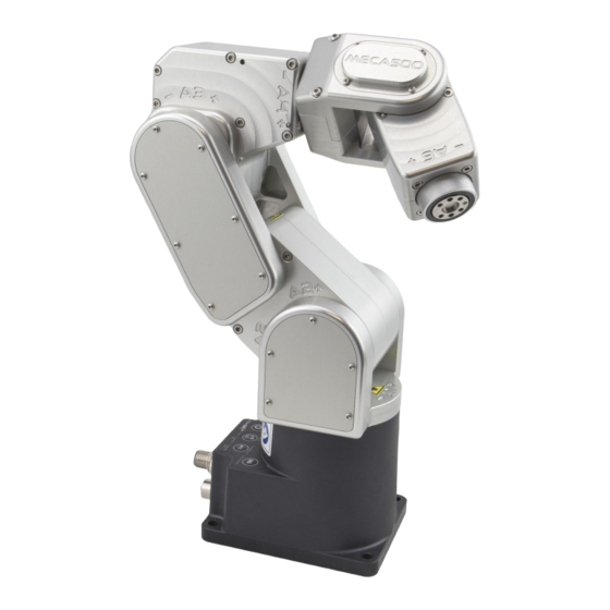
User Manual What’s inside the box Your shipping box contains a Meca500 robot arm (Fig. 1a), a 2-meter Ethernet cable (Fig. 1b, model MDE45-4MP-RJ45-2M from Mencom Corp.), and a desktop 24 V DC power supply (Fig. 1c) with IEC 320 C14 connector. (You must provide your own AC power cord.) Your box may also contain the MEGP 25 electric gripper. -
Page 7: Safety
User Manual Safety The Meca500 weighs less than 5 kg. It can, however, move relatively fast and may cause injuries, especially when certain end-effectors are attached to its flange (e.g., a sharp tool or a laser). The robot also has pinch regions where two adjacent links of the robot can squeeze a finger (Fig. -
Page 8: Installing A Category 0 Emergency Stop
Installing a Category 0 emergency stop The Meca500 can be equipped with an emergency stop of Category 0 only. Such a stop must be installed on the AC part of the power supply, e.g., by modifying the IEC power cord. -
Page 9: Installing The Meca500
User Manual Installing the Meca500 You are surely eager to start using your Meca500. It is, however, imperative that you fix solidly the base of your robot arm before activating the robot. WARNING: Fix securely the robot’s base via the mounting holes (Fig. 3a) with M6 screws, in either upright or downright position, on a horizontal, flat surface of a rigid,... - Page 10 7. Open a web browser, the latest version of either Google Chrome or Firefox only, and type Meca500’s default IP address 192.168.0.100 in the address bar. 8. Meca500’s web interface should load instantaneously. If it doesn’t, repeat the previous step with a different browser.
-
Page 11: Installing An End-Effector
User Manual. If you want to use any other end-effector with the Meca500, you will need to control it independently from the Meca500. You can attach the cabling of your end-effector along the robot arm using adhesive-backed tie mounts. Finally, you must fix the end-effector to the robot’s flange (Fig. - Page 12 (a) Dimensions (b) Closeup Figure 7: The mechanical interface (flange) of the Meca500 Note that when joint 6 is zero degrees, as in Fig. 7b, the stopper pin on the back of the flange is closest to the tool I/O port. In the view of the flange shown in Fig. 7a, the stopper pin would be on the right.
-
Page 13: Operating The Robot
Operating the robot The web interface Meca500’s web interface is more or less the equivalent of the teach pendant’s interfaces of traditional industrial robots. The interface is essentially an HTML 5 web page with JavaScript and WebGL code and the CAD models of the robot links, and potentially the end-effector and the environment (in binary STL format). -
Page 14: Connection And Disconnection
User Manual Figure 8: Overview of Meca500’s web interface 7.1.2 Connection and disconnection Once the web interface is loaded, the first step is to connect it to the robot. So far, you’ve just established an HTTP connection with the robot, but not activated the socket messaging which is the only communication channel for controlling the robot. -
Page 15: The Programming Panel
The programming panel is used mainly for writing and executing very simple programs, i.e., for testing. These programs are sequences of the proprietary commands described in the Programming manual. Meca500’s command interface does not support conditionals, loops, or other flow control statements. The robot only accepts request commands (to get information from the robot) and motion commands (to tell the robot to perform an action). - Page 16 This can be done by selecting the checkbox, in the programming panel. Next, you need to home the robot. Indeed, since the Meca500 is not equipped with truly absolute encoders, it needs to perform a homing procedure every time you activate it.
-
Page 17: The Robot's Log Panel
7.1.5 The CAD models import panel One particularly innovative and original functionality of Meca500’s web interface is the possibility to upload CAD models for the robot’s tool (end-effector) and environment. These models should be in binary STL format. Currently, they serve only for visualization purposes, but in the very near future, they will be used for avoiding mechanical interferences in real time. -
Page 18: Power-Up Procedure
Select the Control option and click Connect. As soon as the robot is connected, you will get the following welcome message in the log panel: [3000][Connected to Meca500 0_x_x.x.x], where the x’s are numbers. Page 14 of 25 Copyright c 2017 by Mecademic Inc. -
Page 19: Activating The Robot
Never forget that the workspace of a general six-axis robot is a very intricate six-dimensional entity, not just a sphere. Page 15 of 25 Copyright c 2017 by Mecademic Inc. - Page 20 Euler angles. Otherwise, you will certainly find working with the Meca500—or any other industrial robot, for that matter— somewhat frustrating. After homing, all joints are at 0 . In this robot position, the robot is in a wrist singularity and you will not be able to move it in Cartesian mode (e.g., by jogging).
-
Page 21: Power-Off Procedure
This can be done in two ways: send a MoveJoints command with all arguments equal to 0 OR click on the Zero All Joints button in the Joints Jog panel. Page 17 of 25 Copyright c 2017 by Mecademic Inc. -
Page 22: Deactivating The Robot
This program is kept, even after power off, until replaced by another one. 7.5.1 Saving the program via the web client interface To save a program, the robot must be deactivated, i.e., the icon must be unchecked. Page 18 of 25 Copyright c 2017 by Mecademic Inc. -
Page 23: Running The Offline Program
LED will be off when the robot is not homed; the LED will flash slowly when the robot is being homed; the LED will be lit continuously when the robot is homed. Page 19 of 25 Copyright c 2017 by Mecademic Inc. -
Page 24: Buttons
When pressing the buttons on the robot’s control panel, keep your fingers away from the pinch points of the robot, and move away from the robot as soon as a button is released. Page 20 of 25 Copyright c 2017 by Mecademic Inc. - Page 25 The brakes will reengage as soon as the 0G button is released. CAUTION: Once the robot is deactivated, hold the robot with one hand, before pressing the 0G button. Otherwise, the robot may fall down under the effect of gravity. Page 21 of 25 Copyright c 2017 by Mecademic Inc.
-
Page 26: Examples
Figure 16 shows the result of each of the four MoveLin commands. (a) MoveLin(140,-100,250,0,90,0) (b) MoveLin(140,100,250,0,90,0) (c) MoveLin(270,100,250,0,90,0) (d) MoveLin(270,-100,250,0,90,0 ) Figure 16: The four separate robot positions that define the motion sequence Page 22 of 25 Copyright c 2017 by Mecademic Inc. -
Page 27: Troubleshooting
2. Hold the power button pressed until the Power, Home and Play LEDs, each flash three times. CAUTION: Never disassemble the robot. The robot requires no maintenance, and if you think it is damaged, stop using it immediately and contact us. Page 23 of 25 Copyright c 2017 by Mecademic Inc. -
Page 28: Storing The Robot In Its Shipping Box
[3000][Connected to Meca500 x_x_x.x.x]. Storing the robot in its shipping box To put the Meca500 back into the foam insert of its original shipping box, send the command MoveJoints(0,-60,60,0,0,0) or jog the robot’s joints 1, 2 and 3 to 0 , 60 , and 60 , respectively. -
Page 29: Ec Declaration Of Incorporation (Original)
1300 Saint-Patrick Montreal, QC H3K 1A4 Canada hereby declares that the product described below Product designation: Extra-small six-axis industrial robot Meca500 Type: Meca500-R2 meets the applicable basic safety requirements of the Machinery Directive 2006/42/EC. This partly completed machinery may not be put into operation until conformity of the... - Page 30 Mecademic Inc. 1300 Saint-Patrick St Montreal QC H3K 1A4 CANADA...
Need help?
Do you have a question about the Meca500 and is the answer not in the manual?
Questions and answers