Table of Contents
Advertisement
Quick Links
915GL-M7 Ultra
FCC Information and Copyright
This equipment has been tes ted and found to comply with the limits of a Class
B digital devic e, purs uant to Part 15 of the FCC Rules . T hese limits are designed
to provide reasonable protec tion against harmful interference in a residential
installation. T his equipment generates , uses and can radiate radio frequency
energy and, if not ins talled and used in accordance with the instructions , may
cause harmful interference to radio communications . There is no guarantee
that interference will not occur in a particular ins tallation.
The vendor makes no representations or warranties with respec t to the
contents here and s pecially disclaims any implied warranties of merchantability
or fitness for any purpose. Further the vendor reserves the right to revise this
publication and to make c hanges to the c ontents here without obligation to
notify any party beforehand.
D uplication of this publication, in part or in whole, is not allowed without first
obtaining the vendor's approval in writing.
The content of this user's manual is subject to be c hanged without notice and
we will not be res ponsible for any mis takes found in this user's manual. All the
brand and produc t names are trademarks of their respec tive companies .
i
Advertisement
Chapters
Table of Contents

Subscribe to Our Youtube Channel
Related Manuals for Biostar 915GL-M7 Ultra


Summary of Contents for Biostar 915GL-M7 Ultra
- Page 1 915GL-M7 Ultra FCC Information and Copyright This equipment has been tes ted and found to comply with the limits of a Class B digital devic e, purs uant to Part 15 of the FCC Rules . T hese limits are designed to provide reasonable protec tion against harmful interference in a residential installation.
-
Page 2: Table Of Contents
Table of Contents Chapter 1: Introduction ............1 Motherboard Features ..........1 Package Checklist............4 Motherboard Layout ............ 5 Chapter 2: Hardware Installation ..........6 Central Processing Unit (CPU)........6 FAN Headers............... 7 Memory Module Installation ......... 9 Connectors and Slots ...........10 Chapter 3: Headers &... -
Page 3: Chapter 1: Introduction
915GL-M7 Ultra CHAPTER 1: INTRODUCTION OTHERBOARD EATURES A. Hardware Supports socket 775. Supports Intel Pentium 4 /Celeron D processor. Front side bus at the following frequency ranges: 533 MT/s (133 MHz Core Clock) 800 MT/s (200 MHz Core Clock) Supports Hyper-Threading Technology. - Page 4 915GL-M7 Ultra Se rial ATA Controller integrated in ICH6. Supports 4 Serial ATA (SATA) ports. Intel Advanced Host Controller (AHCI). Compliant with SATA 1.0 specification Data transfer rates up to 1.5Gb/s Slots Two 32-bit PCI bus master slots. One PCI-Extreme (PCI-EX) slot.
- Page 5 915GL-M7 Ultra Front Side On-board Pe ripherals 1 IDE connector supports 2 hard disk devices. 1 front panel header supports front panel facilities. 1 CD-in connector supports 1 CD-ROM audio-in device. 1 front audio header supports front panel audio function.
-
Page 6: Package Checklist
915GL-M7 Ultra B. BIOS & Software BIOS Award legal BIOS. Supports APM1.2. Supports ACPI. Supports USB Function. Software Supports Warpspeeder™, 9th Touch™, WINFLASHER™ and FLASHER™. Offers the highest performance for Windows 98SE, Windows 2000, Windows Me, Windows XP, SCO UNIX etc. -
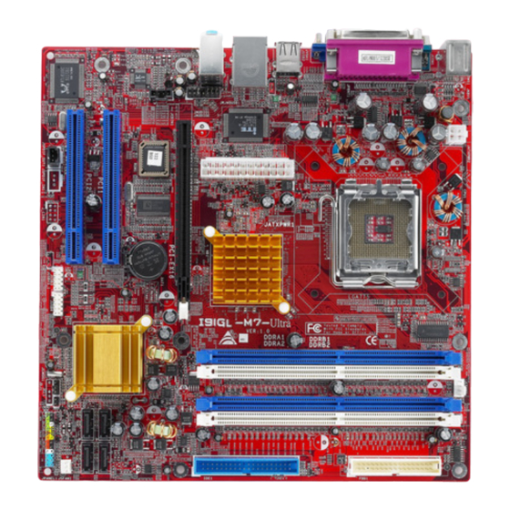
Page 7: Motherboard Layout
915GL-M7 Ultra OTHERBOARD AYOUT P CI -E X BAT1 J _CI R1 JD J1 (optional) (optional) Note: ■ represents the 1 pin. -
Page 8: Chapter 2: Hardware Installation
915GL-M7 Ultra CHAPTER 2: HARDWARE INSTALLATION (CPU) ENTRAL ROCESSING Special Notice: Remove Pin Cap before installation, and make good preservation for future use. When the CPU is removed, cover the Pin Cap on the empty socket to ens ure pin legs won’t be damaged. -
Page 9: Fan Headers
915GL-M7 Ultra Step 2-2: Step 3: Hold the CPU down firmly, and then close the lever to complete the installation. Step 4: Put the CPU Fan on the CPU and buckle it. Connect the CPU FAN power cable to the JCFAN1. This completes the installation. - Page 10 915GL-M7 Ultra wire is Ground and should be connected to GND.
-
Page 11: Memory Module Installation
915GL-M7 Ultra EMORY ODULE NSTALLATION Unlock a DIMM slot by pressing the retaining clips outward. Align a DIMM on the slot such that the notch on the DIMM matches the break on the Slot. Insert the DIMM vertically and firmly into the slot until the retaining... -
Page 12: Connectors And Slots
915GL-M7 Ultra ONNECTORS AND LOTS PCI1/PCI2: Peripheral Component Interconnect Slots This motherboard is equipped with 2 standard PCI slots. PCI stands for Peripheral Component Interconnect, and it is a bus standard for expansion cards. This PCI slot is designated as 32 bits. - Page 13 915GL-M7 Ultra PCI-EX: PCI-Extreme Slot This PCI-EX (PCI-Extreme) slot is a special design for PCI-Express (PCI-E) interface graphic cards. The PCI-EX slot is compliant with PCI-Express 1.0a specification, and bandwidth of data transfer is up to 1GB/s per direction, for an aggregate of 2GB/s totally.
-
Page 14: Chapter 3: Headers & Jumpers Setup
915GL-M7 Ultra CHAPTER 3: HEADERS & JUMPERS SETUP OW TO ETUP UMPERS The illustration shows how to set up jumpers. When the jumper cap is placed on pins, the jumper is “close”, if not, that means the jumper is “open”. - Page 15 915GL-M7 Ultra JSPDIF_O UT1: Digital Audio-out Conne ctor This connector allows user to connect the PCI bracket SPDIF output header. Assignment SPDIF_OUT JSPDIF_OUT1 Ground JSPDIF_IN1 (optional): Digital Audio-in Conne ctor This connector allows user to connect the PCI bracket SPDIF output header.
- Page 16 915GL-M7 Ultra JAUDIO 2: Front Panel Audio Heade r This header allows user to connect the front audio out put cable with the PC front panel. It will disable the output on back panel audio connectors. Assignment Assignment 1 Mic in/center...
- Page 17 915GL-M7 Ultra JPANEL1: Front Panel Heade r This 24-pin connector includes Power-on, Reset, HDD LED, Power LED, Sleep button, speaker and IrDA Connection. It allows user to connect the PC case’s front panel switch functions. PWR_LED On/Off HLED JPANEL1 Assignment...
- Page 18 915GL-M7 Ultra JATXPWR1/JATXPWR2: Powe r Connectors JATXPWR1: This connector allows user to connect with 20-pin power connector on the ATX power supply. JATXPWR2: By connecting this connector, it will provide +12V to CPU power circuit. Assignment Assignment 1 +3.3V 13 +3.3V 2 +3.3V...
-
Page 19: Chapter 4: Useful Help
BIOS contents are corrupted. In this Case, please follow the procedure below to restore the BIOS: 1. Make a bootable floppy disk. 2. Download the Flash Utility “AWDFLASH.exe” from the Biostar website: www.biostar.com.tw 3. Confirm motherboard model and download the respectively BIOS from Biostar website. - Page 20 915GL-M7 Ultra B. CPU Overheated If the system shutdown automatically after power on system for seconds, that means the CPU protection function has been activated. When the CPU is over heated, the motherboard will shutdown automatically to avoid a damage of the CPU, and the system may not power on again.
-
Page 21: Troubleshooting
915GL-M7 Ultra ROUBLESHOOTING Probable Solution No power to the system at all Make sure power cable is Power light don’t illuminate, f an securely plugged in. inside power supply does not turn Replace cable. Contact technical support. Indicator light on key board does not turn on. -
Page 22: Chapter 5: Warpspeeder
915GL-M7 Ultra WARPSPEEDER™ CHAPTER 5: NTRODUCTION [WarpSpeeder™], a new powerful control utility, features three user-friendly functions including Overclock Manager, Overvoltage Manager, and Hardware Monitor. With the Overclock Manager, users can easily adjust the frequency they prefer or they can get the best CPU performance with just one click. The Overvoltage Manager, on the other hand, helps to power up CPU core voltage and Memory voltage. -
Page 23: Installation
915GL-M7 Ultra NSTALLATION 1. Execute the setup execution file, and then the following dialog will pop up. Please click “Next” button and follow the default procedure to install. 2. When you see the following dialog in setup procedure, it means setup is completed. -
Page 24: Warpspeeder™] Includes 1 Tray Icon And 5 Panels
915GL-M7 Ultra ™] PEEDER INCLUDES TRAY ICON AND PANELS 1. Tray Icon: Whenever the Tray Icon utility is launched, it will display a little tray icon on the right side of Windows Taskbar. This utility is responsible for conveniently invoking [WarpSpeeder™] Utility. - Page 25 915GL-M7 Ultra 2. Main Panel If you click the tray icon, [WarpSpeeder™] utility will be invoked. Please refer to the following figure; the utility’s first window you will see is Main Panel. Main Panel contains fe ature s as follows: a.
- Page 26 915GL-M7 Ultra 3. Voltage Panel Click the Voltage button in Main Panel, the button will be highlighted and the Voltage Panel will slide out to up as the following figure. In this panel, you can decide to increase CPU core voltage and Memory voltage or not.
- Page 27 915GL-M7 Ultra 4. Overclock Panel Click the Overclock button in Main Panel, the button will be highlighted and the Overclock Panel will slide out to left as the following figure. O ve rclock Panel contains the these features: a. “–3MHz button”, “-1MHz button”, “+1MHz button”, and “+3MHz button”: provide user the ability to do real-time overclock adjustment.
- Page 28 915GL-M7 Ultra “Auto-overclock button”: User can click this button and [WarpSpeeder™] will set the best and stable performance and frequency automatically. [WarpSpeeder™] utility will execute a series of testing until system fail. Then system will do fail-safe reboot by using Watchdog function. After reboot, the [WarpSpeeder™] utility will restore to the hardware default...
- Page 29 915GL-M7 Ultra 6. About Panel Click the “about” button in Main Panel, the button will be highlighted and the About Panel will slide out to up as the following figure. In this panel, you can get model name and detail information in hints of all the chipset that are related to overclocking.
- Page 30 915GL-M7 Ultra Note : Because the overclock, overvoltage, and hardware monitor features are controlled by several separate chipset, [WarpSpeeder™] divide these features to separate panels. If one chipset is not on board, the correlative button in Main panel will be disabled, but will not interfere other panels’...
- Page 31 915GL-M7 Ultra BIOS SETUP BIOS Setup..................1 1 Main Menu..................... 3 2 Standard CMOS Features ................6 3 Advanced BIOS Features................9 4 Advanced Chipset Features................14 5 Integrated Peripherals .................. 16 6 Power Management Setup ................22 7 PnP/PCI Configurations ................27 8 PC Health Status ..................
-
Page 32: Bios Setup
915GL-M7 Ultra BIOS Manual BIOS Setup Introduction This manual discussed Award™ Setup program built into the ROM BIOS. The Setup program allows users to modify the basic system configuration. This special information is then stored in battery-backed RAM so that it retains the Setup information when the power is turned off. - Page 33 915GL-M7 Ultra BIOS Manual PCI Bus Support This AWARD BIOS also supports Version 2.1 of the Intel PCI (Peripheral Component Interconnect) local bus specification. DRAM Support DDR SDRAM (Double Data Rate Synchronous DRAM) are supported. Supported CPUs This AWARD BIOS supports the Intel CPU.
-
Page 34: Main Menu
915GL-M7 Ultra BIOS Manual 1 Main Menu Once you enter Award BIOS™ CMOS Setup Utility, the Main Menu will appear on the screen. The Main Menu allows you to select from several setup functions. Use the arrow keys to select among the items and press <Enter> to accept and enter the sub-menu. - Page 35 915GL-M7 Ultra BIOS Manual Power Management Setup This submenu allows you to configure the power management features. PnP/PCI Configurations This submenu allows you to configure certain “Plug and Play” and PCI options. PC Health Status This submenu allows you to monitor the hardware of your system.
- Page 36 915GL-M7 Ultra BIOS Manual Save & Exit Setup Save all configuration changes to CMOS (memory) and exit setup. Confirmation message will be displayed before proceeding. Exit Without Saving Abandon all changes made during the current session and exit setup. Confirmation message will be displayed before proceeding.
-
Page 37: Standard Cmos Features
915GL-M7 Ultra BIOS Manual 2 Standard CMOS Features The items in Standard CMOS Setup Menu are divided into 10 categories. Each category includes no, one or more than one setup items. Use the arrow keys to highlight the item and then use the<PgUp>... - Page 38 915GL-M7 Ultra BIOS Manual Main Menu Selections This table shows the selections that you can make on the Main Menu. Item Options Description Date mm : dd : yy Set the system date. Note that the ‘Day’ automatically changes when you set the date.
- Page 39 915GL-M7 Ultra BIOS Manual Item Options Description Halt On All Errors Select the situation in which No Errors you want the BIOS to stop All, but Keyboard the POST process and All, but Diskette notify you. All, but Disk/ Key...
-
Page 40: Advanced Bios Features
915GL-M7 Ultra BIOS Manual 3 Advanced BIOS Features Figure 3. Advanced BIOS Setup CPU FEATURE Delay Prior to Thermal Set this item to enable the CPU Thermal function to engage after the specified time. The Choices: 4, 8, 16 (default), 32. - Page 41 915GL-M7 Ultra BIOS Manual TM2 Bus Ratio Represents the frequency. Bus ratio of the throttled performance state that will be initiated when the on-die sensor goes from not hot to hot. The Choices: 0X (default). TM2 Bus VID Represents the voltage of the throttled performance state that will be initiated when the on-die sensor goes from not hot to hot.
- Page 42 915GL-M7 Ultra BIOS Manual BOOT SEQ & FLOPPY SETUP First/Second/Third/Boot Other Device These BIOS attempt to load the operating system from the device in the sequence selected in these items. The Choices: Floppy, LS120, HDD-0, SCSI, CDROM, HDD-1, HDD-2,HDD-3, ZIP100, LAN, HPT370, Disabled, Enabled.
- Page 43 915GL-M7 Ultra BIOS Manual CPU L3 Cache Depending on the CPU/chipset in use, you may be able to increase memory access time with this option. Enabled (default) Enable cache. Disabled Disable cache. HYPER-THREADING TECHNOLOGY This option allows you to enable or disabled CPU Hyper-Threading.
- Page 44 915GL-M7 Ultra BIOS Manual SECURITY OPTION This option will enable only individuals with passwords to bring the system online and/or to use the CMOS Setup Utility. System A password is required for the system to boot and is also required to access the Setup Utility.
-
Page 45: Advanced Chipset Features
915GL-M7 Ultra BIOS Manual 4 Advanced Chipset Features This submenu allows you to configure the specific features of the chipset installed on your system. This chipset manage bus speeds and access to system memory resources, such as DRAM. It also coordinates communications with the PCI bus. - Page 46 915GL-M7 Ultra BIOS Manual DRAM RAS# PRECHARGE If an insufficient number of cycles is allowed for RAS to accumulate its charge before DRAM refresh, the refresh may be incomplete, and the DRAM may fail to retain data. Fast gives faster performance; and Slow gives more stable performance.
-
Page 47: Integrated Peripherals
915GL-M7 Ultra BIOS Manual 5 Integrated Peripherals Figure 5. Integrated Peripherals OnChip IDE Device IDE HDD Block Mode Block mode is also called block transfer, multiple commands, ormultiple sector read / write. If your IDE hard drive supports block mode (most new drives do), select Enabled... - Page 48 915GL-M7 Ultra BIOS Manual IDE DMA Transfer Access This item allows you to enable or disable the IDE transfer access. The Choices: Enabled (default), Disabled. On-chip Primary PCI IDE This item allows you to enable or disable the primary/ secondary IDE Channel.
- Page 49 915GL-M7 Ultra BIOS Manual ONBOARD DEVICE PCI Express Root Port Func, PCI Express Port 1/ 2/3/4 This item allows you to select the PCI Express Port. The Choices: Auto (default), Enabled, Disabled. PCI-E Compliancy Mode This item allows you to select the PCI-E Compliancy Mode.
- Page 50 915GL-M7 Ultra BIOS Manual USB Controller Select Enabled if your system contains a Universal Serial Bus (USB) controller and you have USB peripherals. The Choices: Enabled (default), Disabled USB 2.0 Controller This entry is to enabled/ disabled EHCI controller only.
- Page 51 915GL-M7 Ultra BIOS Manual Super IO Device Super IO Device If you highlight the literal “Press Enter” next to the “ ” label and then press the enter key, it will take you a submenu with the following options: Onboard FDC Controller Select Enabled if your system has a floppy disk controller (FDC) installed on the system board and you wish to use it.
- Page 52 915GL-M7 Ultra BIOS Manual Onboard Parallel Port This item allows you to determine access onboard parallel port controller with which I/O Address. The Choices: 378/IRQ7 (default), 278/IRQ5, 3BC/IRQ7, Disabled. Parallel Port Mode The default value is SPP. The Choices: SPP (default) Using Parallel port as Standard Printer Port.
-
Page 53: Power Management Setup
915GL-M7 Ultra BIOS Manual 6 Power Management Setup The Power Management Setup Menu allows you to configure your system to utilize energy conservation and power up/power down features. Figure 6. Power Management Setup ACPI & WAKE UP EVENTS ACPI Function This item displays the status of the Advanced Configuration and Power Management (ACPI). - Page 54 915GL-M7 Ultra BIOS Manual ACPI Suspend Type The item allows you to select the suspend type under the ACPI operating system. The Choices: S1 (POS) (default) Power on Suspend S3 (STR) Suspend to RAM S1 & S3 POS+STR Run VGABIOS if S3 Resume Choosing Enabled will make BIOS run VGA BIOS to initialize the VGA card when system wakes up from S3 state.
- Page 55 915GL-M7 Ultra BIOS Manual KB POWER ON Password Input password and press Enter to set the Keyboard power on password. Hot Key Power ON Input password and press Enter to set the Keyboard power on password. The Choices: Ctrl-F1 (default), Ctrl-F2, Ctrl-F3, Ctrl-F4, Ctrl-F5, Ctrl-F6, Ctrl-F7, Ctrl-F8, Ctrl-F9, Ctrl-F10, Ctrl-F11, and Ctrl-F12.
- Page 56 915GL-M7 Ultra BIOS Manual PCI PIRQ [A-D]# You can select to enable or disable PCI PIRQ [A-D]# under this item. The Choices: Disabled (default), Enabled. Power Management This category allows you to select the type (or degree) of power saving and is directly related to the following modes: 1.HDD Power Down.
- Page 57 915GL-M7 Ultra BIOS Manual Suspend Mode The item allows you to select the suspend type under ACPI operating system. The Choices: Disabled (default), 1 Min, 2 Min, 4 Min, 6 Min, 8 Min, 10 Min, 20 Min, 30 Min, 40 Min, 1 Hour.
-
Page 58: Pnp/Pci Configurations
915GL-M7 Ultra BIOS Manual 7 PnP/PCI Configurations This section describes configuring the PCI bus system. PCI, or Personal Computer Interconnect, is a system which allows I/O devices to operate at speeds nearing the speed of the CPU itself uses when communicating with its own special components. This section covers some very technical items and it is strongly recommended that only experienced users should make any changes to the default settings. - Page 59 915GL-M7 Ultra BIOS Manual IRQ RESOURCES This submenu will allow you to assign each system interrupt a type, depending on the type of device using the interrupt. When you press the “Press Enter” tag, you will be directed to a submenu that will allow you to configure the system interrupts.
-
Page 60: Pc Health Status
915GL-M7 Ultra BIOS Manual 8 PC Health Status Figure 8. PC Health Status CPU FAN Control The Choice “smart” can make your CPU FAN to reduce noise. The Choices: Always On, Smart (default). Shutdown Temperature This item allows you to set up the CPU shutdown Temperature. This item only... -
Page 61: Frequency/ Voltage Control
915GL-M7 Ultra BIOS Manual 9 Frequency/ Voltage Control Figure 9. Frequency/ Voltage Control CPU CLOCK RATIO The Choices: 8X (default), 9X, 10X, 11X, 12X, 13X, 14 X, 15X, 16X, 17X, 18X, 19X, 20 X, 21 X, 22 X, and 23X. - Page 62 915GL-M7 Ultra BIOS Manual Method 2: Press the <Insert> key and Power button simultaneously, after that keep-on pressing the <Insert> key until the power-on screen showed. This action will boot-up the system according to FSB of the processor It’s strongly recommended to set CPU Vcore and clock in default setting. If the...
Need help?
Do you have a question about the 915GL-M7 Ultra and is the answer not in the manual?
Questions and answers