Table of Contents
Advertisement
945GC-M7 TE Setup Manual
FCC Information and Copyright
This equipment has been tested and found to comply with the limits of a Class
B digital device, pursuant to Part 15 of the FCC Rules. These limits are designed
to provide reasonable protection against harmful interference in a residential
installation. This equipment generates, uses, and can radiate radio frequency
energy and, if not installed and used in accordance with the instructions, may
cause harmful interference to radio communications. There is no guarantee
that interference will not occur in a particular installation.
The vendor makes no representations or warranties with respect to the
contents here and specially disclaims any implied warranties of merchantability
or fitness for any purpose. Further the vendor reserves the right to revise this
publication and to make changes to the contents here without obligation to
notify any party beforehand.
Duplication of this publication, in part or in whole, is not allowed without first
obtaining the vendor's approval in writing.
The content of this user's manual is subject to be changed without notice and
we will not be responsible for any mistakes found in this user's manual. All the
brand and product names are trademarks of their respective companies.
Advertisement
Table of Contents

Subscribe to Our Youtube Channel
Related Manuals for Biostar 945GC-M7 TE


Summary of Contents for Biostar 945GC-M7 TE
- Page 1 945GC-M7 TE Setup Manual FCC Information and Copyright This equipment has been tested and found to comply with the limits of a Class B digital device, pursuant to Part 15 of the FCC Rules. These limits are designed to provide reasonable protection against harmful interference in a residential installation.
-
Page 2: Table Of Contents
Table of Contents Chapter 1: Introduction ........1 Before You Start ................1 Package Checklist ................1 Motherboard Features..............2 Rear Panel Connectors ..............3 Motherboard Layout................. 4 Chapter 2: Hardware Installation ......5 Installing Central Processing Unit (CPU)........5 FAN Headers.................. -
Page 3: Chapter 1: Introduction
945GC-M7 TE CHAPTER 1: INTRODUCTION EFORE TART Thank you for choosing our product. Before you start installing the motherboard, please make sure you follow the instructions below: Prepare a dry and stable working environment with sufficient lighting. Always disconnect the computer from power outlet before operation. -
Page 4: Motherboard Features
Motherboard Manual OTHERBOARD EATURES SPEC LGA 775 Supports Hyper-Threading Intel Core2Duo / Pentium 4 / Pentium D / Execute Disable Bit Celeron D / Celeron 4xx processor up to 3.8 Enhanced Intel SpeedStep GHz *It is recommended to use processors Extended Memory 64 Technology with 95W power consumption. -
Page 5: Rear Panel Connectors
Provide Audio-In/Out and microphone connection Board Size 190 (W) x 239 (L) mm Micro ATX form Factor Biostar Reserves the right to add or remove support OS Support Windows XP / VISTA for any OS with or without notice. ANEL... -
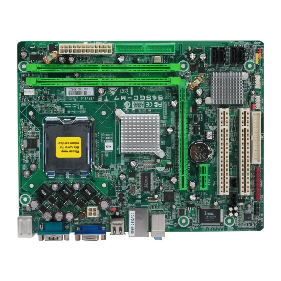
Page 6: Motherboard Layout
Motherboard Manual OTHERBOARD AYOUT JCFAN1 JKBMS1 LGA775 JATXPWR1 CPU1 JATXPWR2 JUSB2 JUSBV1 Intel JRJ45USB1 945GC JAUDIO1 DVIJ1(Optional) PEX16_1 BAT1 JCMOS1 PEX1_1 SATA4 BIOS Intel PCI1 ICH7 JCDIN1 JSPDIF_OUT1 PCI2 SATA1 Codec JUSBV2 JPRNT1 FDD1 JAUDIOF1 JUSB3 JUSB4 JPANEL1 Note: ■ represents the 1 pin. -
Page 7: Chapter 2: Hardware Installation
945GC-M7 TE CHAPTER 2: HARDWARE INSTALLATION (CPU) NSTALLING ENTRAL ROCESSING Special Notice: Remove Pin Cap before installation, and make good preservation for future use. When the CPU is removed, cover the Pin Cap on the empty socket to ensure pin legs won’t be damaged. Pin-Cap Step 1: Pull the socket locking lever out from the socket and then raise the lever up to a 90-degree angle. - Page 8 Motherboard Manual Step 2: Look for the triangular cut edge on socket, and the golden dot on CPU should point forwards this triangular cut edge. The CPU will fit only in the correct orientation. Step 2-1: Step 2-2: Step 3: Hold the CPU down firmly, and then lower the lever to locked position to complete the installation.
-
Page 9: Fan Headers
945GC-M7 TE FAN H EADERS These fan headers support cooling-fans built in the computer. The fan cable and connector may be different according to the fan manufacturer. Connect the fan cable to the connector while matching the black wire to pin#1. -
Page 10: Installing System Memory
Motherboard Manual NSTALLING YSTEM EMORY A. DDR2 Module Unlock a DIMM slot by pressing the retaining clips outward. Align a DIMM on the slot such that the notch on the DIMM matches the break on the Slot. Insert the DIMM vertically and firmly into the slot until the retaining chip snap back in place and the DIMM is properly seated. - Page 11 945GC-M7 TE B. Memory Capacity DIMM Socket DDR2 Module Total Memory Size Location DDR2_A1 256MB/512MB/1GB *1 Max memory 2GB. DDR2_B1 256MB/512MB/1GB *1 C. Dual Channel Memory Installation To trigger the Dual Channel function of the motherboard, the memory module must meet the following requirements: Install memory module of the same density in pairs, shown in the following table.
-
Page 12: Connectors And Slots
Motherboard Manual 2.4 C ONNECTORS AND LOTS FDD1: Floppy Disk Connector The motherboard provides a standard floppy disk connector that supports 360K, 720K, 1.2M, 1.44M and 2.88M floppy disk types. This connector supports the provided floppy drive ribbon cables. IDE1: Hard Disk Connectors The motherboard has a 32-bit Enhanced PCI IDE Controller that provides PIO Mode 0~4, Bus Master, and Ultra DMA 33/66/100 functionality. - Page 13 945GC-M7 TE PEX16_1: PCI-Express x16 Slot PCI-Express 1.0a compliant. Maximum theoretical realized bandwidth of 4GB/s simultaneously per direction, for an aggregate of 8GB/s totally. PEX1_1: PCI-Express x1 Slot PCI-Express 1.0a compliant. Data transfer bandwidth up to 250MB/s per direction; 500MB/s in total. PCI-Express supports a raw bit-rate of 2.5Gb/s on the data pins.
-
Page 14: Chapter 3: Headers & Jumpers Setup
Motherboard Manual CHAPTER 3: HEADERS & JUMPERS SETUP OW TO ETUP UMPERS The illustration shows how to set up jumpers. When the jumper cap is placed on pins, the jumper is “close”, if not, that means the jumper is “open”. Pin opened Pin closed Pin1-2 closed... - Page 15 945GC-M7 TE JATXPWR1: ATX Power Source Connector This connector allows user to connect 24-pin power connector on the ATX power supply. Assignment +3.3V +3.3V Ground Ground Ground PW_OK Standby Voltage +5V +12V +12V 2 x 12 Detect +3.3V -12V Ground PS_ON Ground Ground...
- Page 16 Motherboard Manual JUSB3/JUSB4: Headers for USB 2.0 Ports at Front Panel This motherboard provides 2 USB 2.0 headers, which allows user to connect additional USB cable on the PC front panel, and also can be connected with internal USB devices, like USB card reader. Assignment +5V (fused) +5V (fused)
- Page 17 945GC-M7 TE JSPDIF_OUT1: Digital Audio out Connectors This connector allows user to connect the PCI bracket SPDIF output header. Assignment SPDIF_OUT1 Ground JAUDIOF1: Front Panel Audio Header This header allows user to connect the front audio output cable with the PC front panel.
-
Page 18: Clear Cmos Procedures
Motherboard Manual JCDIN1: CD-ROM Audio-in Connector This connector allows user to connect the audio source from the variaty devices, like CD-ROM, DVD-ROM, PCI sound card, PCI TV turner card etc.. Assignment Left Channel Input Ground Ground Right Channel Input JCMOS1: Clear CMOS Header By placing the jumper on pin2-3, it allows user to restore the BIOS safe setting and the CMOS data, please carefully follow the procedures to avoid damaging the motherboard. - Page 19 945GC-M7 TE DVIJ1: Connector for DVI Daughter Card Adapter (Optional) This connector is for the specific DVI adapter, which is equipped with a DVI-D connector. With the adapter you can use the DVI-D interface for a better display quality. Moreover, the original D-SUB and the additional DVI-D can be utilized simultaneously, so two panels can disaply simultaneously.
- Page 20 Motherboard Manual JPRNT1: Printer Port Connector This header allows you to connector printer on the PC. Assignment Assignment -Strobe Ground -ALF Data 6 Data 0 Ground -Error Data 7 Data 1 Ground -Init -ACK Data 2 Ground -Scltin Busy Data 3 Ground Ground Data 4...
-
Page 21: Chapter 4: Useful Help
945GC-M7 TE CHAPTER 4: USEFUL HELP RIVER NSTALLATION After you installed your operating system, please insert the Fully Setup Driver CD into your optical drive and install the driver for better system performance. You will see the following window after you insert the CD The setup guide will auto detect your motherboard and operating system. -
Page 22: Award Bios Beep Code
Motherboard Manual BIOS B WARD Beep Sound Meaning One long beep followed by two short Video card not found or video card beeps memory bad High-low siren sound CPU overheated System will shut down automatically One Short beep when system boot-up No error found during POST Long beeps every other second No DRAM detected or install... -
Page 23: Troubleshooting
945GC-M7 TE ROUBLESHOOTING Probable Solution No power to the system at all Make sure power cable is Power light don’t illuminate, fan securely plugged in. inside power supply does not turn Replace cable. Contact technical support. Indicator light on keyboard does not turn on. -
Page 24: Chapter 5: Warpspeeder™ Iii
Motherboard Manual WARPSPEEDER™ III CHAPTER 5: NTRODUCTION [WarpSpeeder™ III], a new powerful control utility, features three user-friendly functions including Overclock Manager, Overvoltage Manager, and Hardware Monitor. With the Overclock Manager, users can easily adjust the frequency they prefer or they can get the best CPU performance with just one click. The Overvoltage Manager, on the other hand, helps to power up CPU core voltage and Memory voltage. -
Page 25: Installation
945GC-M7 TE NSTALLATION 1. Execute the setup execution file, and then the following dialog will pop up. Please click “Next” button and follow the default procedure to install. 2. When you see the following dialog in setup procedure, it means setup is completed. -
Page 26: Warpspeeder™ Iii
Motherboard Manual ™ III PEEDER 1. Desktop Icon After the [WarpSpeeder™ III] has been installed, a [WarpSpeeder™ III] icon will appear on the desktop, just like the icon shown below. Now you can launch the [WarpSpeeder™ III] utility simply by double-clicking the desktop icon. - Page 27 945GC-M7 TE 3. Overclock/Overvoltage Panel Click the Overclock/Overvoltage button in the Main Panel, the button will be highlighted and the Overclock/Overvoltage Panel will show up as the following figure. As you can see, the Overclock Panel is on the right side, and the Overvoltage Panel is on the left side.
- Page 28 Motherboard Manual Overclock Panel contains these features: a. “Auto-Overclock”: User can click this button and [WarpSpeeder™ III] will set the best and stable performance and frequency automatically. A warning dialog as below will show up to notify you that the system may become unstable, click on “OK”...
- Page 29 945GC-M7 TE Overvoltage Panel contains these features: a. “CPU Voltage”: This function allows user to adjust CPU voltage. Click on “+” to increase or “-“ to decrease the CPU voltage. b. “Memory Voltage”: This function allows user to adjust Memory voltage. Click on “+” to increase or “-“...
- Page 30 Motherboard Manual 5. About Panel Click the “about” button in Main Panel, the button will be highlighted and the About Panel will show up as the following figure. In this panel, you can get model name and detail information in hints of all the chipset that are related to overclocking.
- Page 31 945GC-M7 TE This page is intentionally left blank.
-
Page 32: Appendencies: Spec In Other Language
Motherboard Manual APPENDENCIES: SPEC IN OTHER LANGUAGE ERMAN Spezifikationen LGA 775 Intel Core2Duo / Pentium 4 / Pentium D / Unterstützt Hyper-Threading Celeron D / Celeron 4xx Prozessoren mit bis zu Execute Disable Bit 3,8 GHz Enhanced Intel SpeedStep® *It is recommended to use processors with Extended Memory 64 Technology 95W power consumption. - Page 33 PS/2-Maus Serieller Anschluss Rückseiten-E VGA-Anschluss LAN-Anschluss USB-Anschluss Audioanschluss Platinengröße 190 mm (B) X 239 mm (L) Biostar behält sich das Recht vor , ohne OS-Unterstüt Windows XP / VISTA Ankündigung die Unterstützung für ein zung Betriebssystem hinzuzufügen oder zu entfernen.
-
Page 34: France
Motherboard Manual RANCE SPEC LGA 775 Prend en charge les technologies Processeurs Intel Core2Duo / Pentium 4 / Hyper-Threading Pentium D / Celeron D / Celeron 4xx jusqu'à 3,8 d'exécution de bit de désactivation Intel SpeedStep® optimisée *It is recommended to use processors with 95W de mémoire étendue 64 power consumption. - Page 35 Port LAN Port USB Fiche audio Dimensions 190mm (l) X 239 mm (H) de la carte Biostar se réserve le droit d'ajouter ou de Support SE Windows XP / VISTA supprimer le support de SE avec ou sans préavis.
-
Page 36: Italian
Motherboard Manual TALIAN SPECIFICA LGA 775 Processore Intel Core2Duo / Pentium 4 / Supporto di Hyper-Threading Pentium D / Celeron D / Celeron 4xx fino a Execute Disable Bit 3.8 GHz Enhanced Intel SpeedStep® *It is recommended to use processors with 95W Tecnologia Extended Memory 64 power consumption. - Page 37 Porta LAN Porta USB Connettore audio Dimension 190 mm (larghezza) x 239 mm (altezza) i scheda Sistemi Biostar si riserva il diritto di aggiungere o operativi Windows XP / VISTA rimuovere il supporto di qualsiasi sistema supportati operativo senza preavviso.
-
Page 38: Spanish
Motherboard Manual PANISH Especificación LGA 775 Procesador Intel Core2Duo / Pentium 4 / Admite Hyper-Threading Pentium D / Celeron D / Celeron 4xx hasta Bit de deshabilitación de ejecución 3,8 GHz Intel SpeedStep® Mejorado *It is recommended to use processors with Tecnología Extended Memory 64 95W power consumption. - Page 39 Conector de sonido Tamaño de 190 mm. (A) X 239 mm. (H) la placa Soporte de Biostar se reserva el derecho de añadir o retirar el sistema Windows XP / VISTA soporte de cualquier SO con o sin aviso previo. operativo...
-
Page 40: Portuguese
Motherboard Manual ORTUGUESE ESPECIFICAÇÕES LGA 775 Suporta as tecnologias Hyper-Threading Processador Intel Core2Duo / Pentium 4 / Execute Disable Bit Pentium D / Celeron D / Celeron 4xx até 3,8 GHz Enhanced Intel SpeedStep® *It is recommended to use processors with 95W Extended Memory 64 power consumption. - Page 41 Porta USB Tomada de audio Tamanho 190 mm (L) X 239 mm (A) da placa Sistemas A Biostar reserva-se o direito de adicionar ou operativos Windows XP / VISTA remover suporte para qualquer sistema suportados operativo com ou sem aviso prévio.
-
Page 42: Polish
Motherboard Manual OLISH SPEC LGA 775 Obsługa Hyper-Threading Procesor Intel Core2Duo / Pentium 4 / Pentium D Execute Disable Bit Procesor / Celeron D / Celeron 4xx do 3,8 GHz Enhanced Intel SpeedStep® *It is recommended to use processors with 95W Extended Memory 64 Technology power consumption. - Page 43 Port szeregowy Back Panel Port VGA Port LAN Port USB Gniazdo audio Wymiary 190 mm (S) X 239 mm (W) płyty Obsluga Biostar zastrzega sobie prawo dodawania lub systemu Windows XP / VISTA odwoływania obsługi dowolnego systemu operacyjne operacyjnego bez powiadomienia.
-
Page 44: Russian
Motherboard Manual USSIAN СПЕЦ LGA 775 Поддержка технологий Hyper-Threading Процессор Intel Core2Duo / Pentium 4 / (центральн Execute Disable Bit Pentium D / Celeron D / Celeron 4xx до 3.8 ГГц ый Enhanced Intel SpeedStep® *It is recommended to use processors with 95W процессор) Extended Memory 64 Technology power consumption. - Page 45 ввода-выв Порт LAN ода USB-порт Гнездо для подключения наушников Размер 190 мм (Ш) X 239 мм (В) панели Biostar сохраняет за собой право добавлять Поддержка Windows XP / VISTA или удалять средства обеспечения для OS с или без предварительного уведомления.
-
Page 46: Arabic
Motherboard Manual RABIC اﻟﻤﻮاﺻﻔﺎت LGA 775 ﺕﺪﻋﻢ ﺕﻘﻨﻴﺎتHyper-Threading ﻡﻌﺎﻟﺠﺎتIntel Core2Duo / Pentium 4 / Pentium D / Execute Disable Bit وﺣﺪة اﻟﻤﻌﺎﻟﺠﺔ Celeron D / Celeron 4xx ﺝﻴﺠﺎ هﺮﺕﺰ ﺼﻞ إﻟﻰ ﻳ ﺘﺮدد ﺑ Enhanced Intel SpeedStep® اﻟﻤﺮآﺰﻳﺔ *It is recommended to use processors with 95W Extended Memory 64 Technology power consumption. -
Page 47: Smart Fan
ﻡﻨﻔﺬ اﻟﻠﻮﺣﺔ اﻟﺨﻠﻔﻴﺔ ﻋﺪد ﻡﻨﻔﺬ ﺵﺒﻜﺔ اﺕﺼﺎل ﻡﺤﻠﻴﺔ ﻋﺪد ﻡﻨﺎﻓﺬ ﻋﺪد ﻡﻘﺒﺲ ﺹﻮت ارﺕﻔﺎع ﻡﻢ ﻋﺮض ﻡﻢ ﺣﺠﻢ اﻟﻠﻮﺣﺔ ﺕﺤﺘﻔﻆBiostar ﺑﺤﻘﻬﺎ ﻓﻲ إﺿﺎﻓﺔ أو إزاﻟﺔ اﻟﺪﻋﻢ ﻷي ﻥﻈﺎم ﺕﺸﻐﻴﻞ ﺑﺈﺥﻄﺎر أو Windows XP / VISTA دﻋﻢ أﻥﻈﻤﺔ اﻟﺘﺸﻐﻴﻞ ﺑﺪون إﺥﻄﺎر... -
Page 48: Japanese
Motherboard Manual APANESE 仕様 LGA 775 Hyper-Threading Intel Core2Duo / Pentium 4 / Pentium D / Execute Disable Bit Celeron D / Celeron 4xx processor up to 3.8 GHz Enhanced Intel SpeedStep® *It is recommended to use processors with 95W Extended Memory 64 Technology power consumption. - Page 49 CDインコネクタ CDオーディオイン機能をサポートします オンボードコ S/PDIFアウトコネクタ ネクタ デジタルオーディオアウト機能をサポートします CPUファンヘッダ CPUファン電源装置(スマートファン機能を搭載) システムファンヘッダ システムファン電源装置 CMOSクリアヘッダ 各コネクタは2つのフロントパネルUSBポートをサポ USBコネクタ ートします 電源コネクタ(24ピン) 電源コネクタ(4ピン) PS/2キーボード PS/2マウス シリアルポート 背面パネル VGAポート LANポート USBポート オーディオジャック ボードサイズ 190 mm (幅) X 239 mm (高さ) Biostarは事前のサポートなしにOSサポートを追加ま OSサポート Windows XP / VISTA たは削除する権利を留保します。 2011/10/13...
Need help?
Do you have a question about the 945GC-M7 TE and is the answer not in the manual?
Questions and answers