Advertisement
Quick Links
call our customer service department at 1-888-909-3888, between 7:30am and 4:30pm
PST, Monday through Friday.
CAUTION:
Installer: Leave the manual instructions
to the user for future use.
Consumer: Please keep this manual
for future reference.
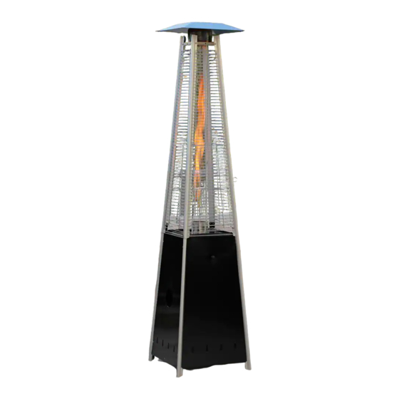
Model#: SRPH98
Read the instructions before use.
This appliance must be installed in
accordance with such regulations as
are in force.
Before returning to your retailer
Advertisement

Related Manuals for Heatmaxx SRPH98


Summary of Contents for Heatmaxx SRPH98
- Page 1 Installer: Leave the manual instructions to the user for future use. Consumer: Please keep this manual for future reference. Model#: SRPH98 Read the instructions before use. This appliance must be installed in accordance with such regulations as are in force.
- Page 2 Certification 89.5" (2.27m) Height Rated heat input 40,000 BTU/hr Fuel Propane Gas Supply n i l Manifold pressure " 1 u l i - i t t l i t c t i Safety features Gas supply pressure Max. 250 PSI, Min. 5 PSI...
- Page 3 The installation must conform with local codes or, in the absence of local codes, with the National Fuel Gas Code, ANSI Z223.1/NFPA 54, NFPA58 Natural Gas and Propane Installation Code, CSA B149.1, or Propane Storage and Handling Code, B149.2 The heater, when installed, must be electrically grounded in accordance with local codes or, in the absence of local codes, with the National Electrical Code, ANSI/NFPA 70, or the Canadian...
- Page 4 Within a partial enclosure which includes an The pressure regulator and hose assembly sup- overhead cover and three side walls, as long as plied with the appliance must be used, replace- 30 percent or more of the horizontal periphery of ment pressure regulators and hose assemblies the enclosure is permanently open.
- Page 5 Perform a leak test with a soapy solution: 1. To check gas connections. 2. After connecting a new cylinder. 3. Upon re-assembly after disassembly. This heater is designed to operate with a standard 20 Ib propane cylinder with Approved Cylinder Connection.
- Page 7 Part # Description Picture Description Picture Part # M5 Wing Nut Reflector M5 Stud Upper Plate M5 x 12 Screw Mesh M5 Nut Guard Bracket Spiral M5 Bolt Burner Assembly Handle Back Panel M4 x 25 Screw (pre-assembly) Gas Cylinder Holder M8 x 10 Screw Fire Damper (pre-assembly)
- Page 8 Unscrew the pre-assembled screws, nuts and washers on the wheel assembly (#17), then attach the wheel assembly (#17) to the bottom plate (#16) with (3) M8 x 10 screws (II), (3) M8 nuts (JJ) and (3) 8.5 washers (KK) as illustrated. M8 x 10 Screw 3 pcs (pre-assembly)
- Page 9 Unscrew the pre-assembled M4 x 25 screws (HH) on the glass tube base (#11), then remove the glass tube base (#11) from the middle plate (#12), and put the M4 x 25 screws (HH) and the glass tube base (#11) aside for Step 7.
- Page 10 Attach the upper plate (#2) to the upper supports (#9) with (8) M5 x 12 screws (CC) as illustrated. M5 x 12 Screw 8 pcs Attach the fire damper (#8) to the upper plate (#2) with (3) M5 bolts (FF) and (3) M5 nuts (DD), then attach the reflector (#1) to the fire damper (#8) with (3) M5 wing nuts (AA) and (3) M5 studs (BB) as illustrated.
- Page 11 Attach the glass tube base (#11) to the middle plate (#12) with (4) M4 x 25 screws (HH) as illustrated. M4 x 25 Screw 4 pcs (pre-assembly) Attach the spiral (#4) to the burner assembly (#5) with (2) M5 x 12 screws (CC), then attach the burner assembly (#5) to the middle plate (#12) with (4) M5 x 12 screws (CC) as illustrated.
- Page 12 Attach the gas cylinder holder (#7) to the back panel (#6) with (2) M5 x 12 screws (CC) as illustrated M5 x 12 Screw 2 pcs Attach the back panel (#6), left and right panel (#14) to the lower supports (#13) with (12) M5 x 12 screws (CC) as illustrated.
- Page 13 Place the glass tube (#10) by guiding it up to insert the upper end through the center hole in the upper plate. Do not force the tube. Slide the bottom end into place and settle it into the hole in the glass tube base. Ensure that the Glass Tube is positioned properly to cover the spiral.
- Page 14 Unscrew the pre-assembled M4 x 10 screw (LL) on the handle (GG), then attach the handle (GG) to the front panel (#15) with M4 x 10 screw (LL). Install the front panel (#15) by inserting the two tabs at the bottom into the holes on the front of the bottom plate (#16).
- Page 15 When installing an LPG cylinder, it may be easier to remove the Front Panel completely and set aside. Place the cylinder on the Bottom Plate. Connect the gas hose to 20lb LPG cylinder (not included). Screw the regulator to the cylinder as illustrated. Tighten securely with the Fastening Belt. The regulator with gas hose is supplied.
- Page 16 All connection on the patio heater have been checked for leakage at the factory. Follow these steps to check the gas hose/regulator/cylinder connections: 1) Make leakage solution by mixing 1 part liquid dish soap and 3 parts water. 2) Spoon or brush several drops (or use squirt bottle) of the solution onto hose connection, regulator &...
- Page 17 Unscrew the cap of the igniter placed on the control box and insert the included AAA battery with the POSITIVE end facing out.
- Page 18 1. Make sure control knob is in the “OFF” position. 2. Turn LP cylinder gas valve to fully open position. 3. Push in control knob and turn counter-clockwise to "IGNITE" position, at the same time push in the ignition button and keep the control knob depressing until lighting the burner.
- Page 19 36'' This heater is primarily used for the heating of outdoor patios, decks, spas, pools and 24'' 24'' open working areas. Combustible materials are considered to be wood, compressed parter, plant fibres, plas- tic or other materials that are capable of being ignited and burned.
- Page 20 WARNING: To enjoy years of outstanding performance from your FOR YOUR SAFETY ; heater make sure you perform the following maintenance DO NOT touch or move heater for activities on a regular basis: at least 45 minutes after use. Allow Keep exterior surfaces clean.
- Page 21 Spiders and insects can nest in burner or orifices. This dangerous condition can damage heater and render it unsafe for use. Clean burner holes by using a heavy-duty wait until heater is cool before pipe cleaner. Compressed air may help clear away covering.
- Page 22 Cylinder valve is closed Open valve Clean or replace orifice or Blockage in orifice or pilot tube pilot tube Open gas line and bleed it Pilot won’t light Air in gas line (pressing control knob in) for not more than 1 - 2 minutes or until you smell gas Low gas pressure with cylinder valve Turn cylinder valve OFF and replace...
- Page 23 The appliance has been manufactured under the highest standards of quality and workmanship. We warrant to the original consumer purchaser that all aspects of this product will be free of defects in material and workmanship for one (1) year from the date of purchase. A replacement for any defective part will be supplied free of charge for installation by the consumer.
Need help?
Do you have a question about the SRPH98 and is the answer not in the manual?
Questions and answers