
Subscribe to Our Youtube Channel
Related Manuals for Asus AAEON UP Squared V2


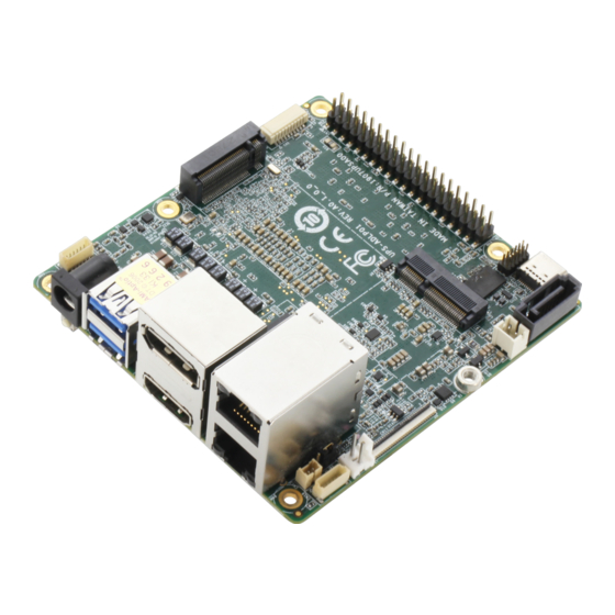
Summary of Contents for Asus AAEON UP Squared V2
- Page 1 UP Squared V2 Maker Board UPS-EHL01 User’s Manual 1 Last Updated: August 29, 2022...
- Page 2 Copyright Notice This document is copyrighted, 2022. All rights are reserved. The original manufacturer reserves the right to make improvements to the products described in this manual at any time without notice. No part of this manual may be reproduced, copied, translated, or transmitted in any form or by any means without the prior written permission of the original manufacturer.
- Page 3 Acknowledgement All other products’ name or trademarks are properties of their respective owners. Microsoft®, Windows® are registered trademarks of Microsoft Corp. ⚫ Intel®, Pentium®, and Celeron® are registered trademarks of Intel Corporation ⚫ Intel Atom™ is a trademark of Intel Corporation ⚫...
- Page 4 Packing List Before setting up your product, please make sure the following items have been shipped: Item Quantity UPS-EHL01 with Heatsink (UP Squared V2) ⚫ If any of these items are missing or damaged, please contact your distributor or sales representative immediately.
- Page 5 About this Document This User’s Manual contains all the essential information, such as detailed descriptions and explanations on the product’s hardware and software features (if any), its specifications, dimensions, jumper/connector settings/definitions, and driver installation instructions (if any), to facilitate users in setting up their product. Users may refer to the product page at AAEON.com for the latest version of this document.
- Page 6 Safety Precautions Please read the following safety instructions carefully. It is advised that you keep this manual for future references All cautions and warnings on the device should be noted. Make sure the power source matches the power rating of the device. Position the power cord so that people cannot step on it.
- Page 7 If any of the following situations arises, please the contact our service personnel: Damaged power cord or plug Liquid intrusion to the device iii. Exposure to moisture Device is not working as expected or in a manner as described in this manual The device is dropped or damaged Any obvious signs of damage displayed on the device...
- Page 8 FCC Statement This device complies with Part 15 FCC Rules. Operation is subject to the following two conditions: (1) this device may not cause harmful interference, and (2) this device must accept any interference received including interference that may cause undesired operation.
- Page 9 China RoHS Requirements (CN) 产品中有毒有害物质或元素名称及含量 AAEON Main Board/ Daughter Board/ Backplane 有毒有害物质或元素 部件名称 铅 汞 镉 六价铬 多溴联苯 多溴二苯醚 (Pb) (Hg) (Cd) (Cr(VI)) (PBB) (PBDE) 印刷电路板 ○ ○ ○ ○ ○ ○ 及其电子组件 外部信号 ○ ○ ○ ○ ○ ○ 连接器及线材...
- Page 10 China RoHS Requirement (EN) Poisonous or Hazardous Substances or Elements in Products AAEON Main Board/ Daughter Board/ Backplane Poisonous or Hazardous Substances or Elements Hexavalent Polybrominated Polybrominated Component Lead Mercury Cadmium Chromium Biphenyls Diphenyl Ethers (Pb) (Hg) (Cd) (Cr(VI)) (PBB) (PBDE) PCB &...
-
Page 11: Table Of Contents
Table of Contents Chapter 1 - Product Specifications..................1 Specifications ......................2 Chapter 2 – Hardware Information ..................4 Dimensions ....................... 5 Jumpers and Connectors ..................6 List of Jumpers and Connectors ................8 2.3.1 PWR Button (SW1) ..................9 2.3.2 BIOS Prog (CN1) .................. - Page 12 Chapter 3 – Software Installation ..................26 Linux Setup ......................27 Windows Drivers Installation ................27 Unknown Device Troubleshooting ..............28 Appendix A – UP Framework SDK Installation ..............30 Introduction ......................31 Installation for Windows 10................... 31 Installation for Windows IoT Core ..............34 Appendix B –...
-
Page 13: Chapter 1 - Product Specifications
Chapter 1 Chapter 1 - Product Specifications... -
Page 14: Specifications
Specifications System Intel® Celeron® N6210 Pentium® J6426 Processor SoC Graphics Intel® UHD Graphics Memory Up to 16GB LPDDR4 Storage Up to 64GB EMMC HDMI 1.4b x 1 DP 1.2 x 1 eDP 1.3 x 1 Audio 6-pin wafer (Line out + MIC in) x 1 RS-232/422 6-pin header x 1 Camera USB 2.0 x 2 (from 10-PIN wafer x 1) - Page 15 System OS Support Microsoft Windows 10 (full) Windows IOT Core Ubuntu 20.04 LTS Yocto 3.1 Power Requirements Power 12V DC-in, 5A Power Supply Type AT/ATX Power Consumption (Typical) 30~38W Mechanical Dimension 3.37" x 3.54" (85.6mm × 90mm) Net Weight 0.52 lbs. (0.24kg) Gross Weight 0.66 lbs.
-
Page 16: Chapter 2 - Hardware Information
Chapter 2 – Hardware Information Chapter 2... -
Page 17: Dimensions
Dimensions Chapter 2 – Hardware Information... -
Page 18: Jumpers And Connectors
Jumpers and Connectors Top: Chapter 2 – Hardware Information... - Page 19 Bottom: Chapter 2 – Hardware Information...
-
Page 20: List Of Jumpers And Connectors
List of Jumpers and Connectors Please refer to the table below for all of the board’s connectors that you can configure for your application Label Function PWR button CN19 BIOS Prog USB HEADER M.2 2280 Key-M Power Input USB3.0 HAT 40 DP/HDMI CN10 M.2 2230 Key-E... -
Page 21: Pwr Button (Sw1)
Label Function LED4 LED4 LED5 LED5 Auto-Power Button Selection 2.3.1 PWR Button (SW1) Signal Signal Signal PS_ON_SW Chapter 2 – Hardware Information... -
Page 22: Bios Prog (Cn1)
2.3.2 BIOS Prog (CN1) Signal Signal SPI_BIOS_MISO SPI_BIOS_CLK SPI_BIOS_CS0# +VCC_SPI SPI_BIOS_MOSI 2.3.3 Fan (CN19) Signal Signal FAN_PWR (12V) Chapter 2 – Hardware Information... -
Page 23: Edp (Cn2)
2.3.4 eDP (CN2) Signal Signal +VDD_eDP +VDD_eDP EDP_TXN_2 EDP_TXP_2 EDP_TXN_1 EDP_TXP_1 EDP_TXN_0 EDP_TXP_0 EDP_TXN_3 EDP_TXP_3 EDP_AUXN EDP_AUXP EDP_BKLT_CTRL EDP_BKLT_EN EDP_HPD_N +V12S +V12S +V12S +V12S Chapter 2 – Hardware Information... -
Page 24: Usb Header (Cn3)
2.3.5 USB Header (CN3) Signal Signal USB2_DN6 USB2_DP6 USB2_DN7 USB2_DP7 UART1_RXD UART1_TXD 2.3.6 M.2 2280 M-Key (CN4) Signal Signal +3.3V_NGFF +3.3V_NGFF +3.3V_NGFF Chapter 2 – Hardware Information... - Page 25 Signal Signal +3.3V_NGFF +3.3V_NGFF +3.3V_NGFF +3.3V_NGFF PCIE_P5_RX_DN PCIE_P5_RX_DP PCIE_P5_TX_DN PCIE_P5_TX_DP GPPC_E_4_SATA_DEVSLP_0 SMB_CLK_1V8 PCIE_P4_RX_DN SMB_DATA_1V8 PCIE_P4_RX_DP PCIE_P4_TX_DN PCIE_P4_TX_DP BUF_PLT_RST# PCIE_CLK4_DN WAKE_N PCIE_CLK4_DP Chapter 2 – Hardware Information...
-
Page 26: Power Input (Cn6)
Signal Signal SUS_CLK_CPU +3P3V_NGFF +3P3V_NGFF +3P3V_NGFF 2.3.7 Power Input (CN6) Signal Signal Signal VCC_12V Chapter 2 – Hardware Information... -
Page 27: Usb 3.0 (Cn7)
2.3.8 USB 3.0 (CN7) Signal Signal USB2_ DN1 USB2_ DP1 USB3_RXN_P1 USB3_RXP _P1 USB3_TXN _P1 USB3_TXP _P1 USB2_ DN2 USB2_ DP2 USB3_RXN _P2 USB3_RXP _P2 USB3_TXN_ P2 USB3_TXP_ P2 Chapter 2 – Hardware Information... -
Page 28: Hat 40 (Cn8)
2.3.9 HAT 40 (CN8) Signal Signal 3.3V@0.5A 5V@0.5A I2C1_SDA (GPIO 1) 5V@0.5A I2C1_SCL (GPIO 2) GPIO_ADC (GPIO 3) UART_TXD (GPIO 16) UART_RXD (GPIO 17) UART_RTS (GPIO 4) I2S_BCLK (GPIO 18) GPIO 5 GPIO 6 GPIO 19 3.3V@0.5A GPIO 20 SPI_MOSI (GPIO 7) SPI_MISO (GPIO 8) GPIO 21 SPI_CLK (GPIO 9) -
Page 29: Dp/Hdmi (Cn9)
2.3.10 DP/HDMI (CN9) Signal Signal TXP_DP_0 TXN_DP_0 TXP_DP_1 TXN_DP_1 TXP_DP_2 TXN_DP_2 CLK_DP_D_P CLK_DP_D_N AUX_P AUX_N DP_HPD +3.3V TXP_HDMI_0 TXN_HDMI_0 TXP_HDMI_1 TXN_HDMI_1 TXP_HDMI_2 TXN_HDMI_2 CLK_HDMI_DP CLK_HDMI_DN HDMI_CEC_O DDCCLK DDCDATA Chapter 2 – Hardware Information... -
Page 30: 2230 E-Key (Cn10)
Signal Signal HDMI_HPD 2.3.11 M.2 2230 E-Key (CN10) Signal Signal +3P3VAUX_WIFI USB2_P4_DP +3P3VAUX_WIFI USB2_P4_DN Chapter 2 – Hardware Information... - Page 31 Signal Signal UART0_TXD UART0_CTS PCIE_P6_TXP UART0_RTS PCIE_P6_TXN PCIE_P6_RXP PCIE_P6_RXN PCIE_CLKP0 PCIE_CLKN0 M.2_BTWIFI_SUS_CLK PLT_RST# CLKREQ_N WAKE_N PCIE_P7_TXP PCIE_P7_TXN PCIE_P7_RXP PCIE_P7_RXN +3P3VAUX_WIFI +3P3VAUX_WIFI Chapter 2 – Hardware Information...
-
Page 32: Rs-232/422 (Cn11)
2.3.12 RS-232/422 (CN11) Signal Signal RTS/TX+ RX/RX+ CTS/RX- TX/TX- Chapter 2 – Hardware Information... -
Page 33: Lan (Cn12)
2.3.13 LAN (CN12) Signal Description Signal Description LAN1_ACTLEDN LAN2_ACTLEDN LAN1_ACTLEDP LAN2_ACTLEDP LAN1_LINK1000# LAN2_LINK1000# LAN1_LINK100# LAN2_LINK100# LAN1_MDI0+ LAN2_MDI0+ LAN1_MDI0- LAN2_MDI0- LAN1_MDI1+ LAN2_MDI1+ LAN1_MDI1- LAN2_MDI1- LAN1_MDI2+ LAN2_MDI2+ LAN1_MDI2- LAN2_MDI2- LAN1_MDI3+ LAN2_MDI3+ LAN1_MDI3- LAN2_MDI3- LAN1_DAC LAN2_DAC R10A LAN1_GND R10B LAN2_GND Chapter 2 – Hardware Information... -
Page 34: Usb 3.0 (Cn13)
2.3.14 USB 3.0 (CN13) Signal Signal +V5P0_USB_1 USB2_DN3 USB2_DP3 USB3_RXN3 USB3_RXP3 USB3_TXN3 USB3_TXP3 2.3.15 RTC (CN14) Signal Signal +V3P3A_RTC Chapter 2 – Hardware Information... -
Page 35: Sata (Cn15)
2.3.16 SATA (CN15) Signal Signal SATA_TXP0 SATA_TXN0 SATA_RXN0 SATA_RXP0 2.3.17 SATA Power (CN16) Signal Signal +V5S Chapter 2 – Hardware Information... -
Page 36: Front Panel (Cn17)
2.3.18 Front panel (CN17) Signal Signal SYSRST# PS_ON_SW SYS_LED+ 2.3.19 Audio (CN18) Signal Signal LOUT_R LOUT_L AUD_GND MIC_IN_JD AUDIO-JD MIC_L_CN Chapter 2 – Hardware Information... -
Page 37: Auto-Power Button Selection (Jp1)
2.3.20 Auto-Power Button Selection (JP1) Signal Disable Enable (Default) Chapter 2 – Hardware Information... -
Page 38: Chapter 3 - Software Installation
Chapter 3 Chapter 3 – Software Installation... -
Page 39: Linux Setup
Linux Setup UPS-EHL01 supports Linux operating systems (see Chapter 1 for specifications). For instructions on how to install a Linux OS onto your UPS-EHL01, you can find several guides and tutorials in the wiki section of the UP Board website at https://up-board.org for both installing supported distributions as well as porting your own Linux build. -
Page 40: Unknown Device Troubleshooting
Unknown Device Troubleshooting After installing Windows drivers on UP Squared V2 (UPS-EHL01), you will see some unknown devices shown on device manager. Most unknown devices can be fixed by manually installing the driver from the Intel Serial IO 5.123.1.1023, except for Multimedia Audio Controller but here’s how to fix it: Multimedia Audio Controller To fix the yellow exclamation mark “Multimedia Audio Controller”, please go to BIOS... - Page 41 VEN_AANT&DEV_1280: This is the ADC for Linux, there is no Windows driver. This can be ignored. Chapter 3 – Software Installation...
-
Page 42: Appendix A - Up Framework Sdk Installation
Appendix A Appendix A – UP Framework SDK Installation... -
Page 43: Introduction
Introduction This section provides instructions for the installation of the UP Framework SDK. Instructions are provided for Windows 10 and Windows IoT Core. You can download the latest version of UP Framework SDK from the UP community: https://downloads.up-community.org/download/up-sdk-for-windows-10-and-windows-iot/ A.2 Installation for Windows 10 Step 1 Locate the downloaded file UpFrameworkSetup.msi and run the installer. - Page 44 Step 2 Select the installation folder. Default destination path is C:\Program Files(x86)\AAEON\ You may also choose to install the UP Framework SDK for all users or only the current user. Press “Next” to continue installation. Step 3 Press “Next” to confirm the installation. Appendix A –...
- Page 45 Step 4 Press “Close” to exit once setup is complete. Appendix A – UP Framework SDK Installation...
-
Page 46: A.3 Installation For Windows Iot Core
A.3 Installation for Windows IoT Core Before you begin, make sure you have downloaded and installed the latest version of the Windows IoT Core image from the UP community. Installation requires using a connected PC with the UP Framework SDK software downloaded and saved. - Page 47 Step 2 Download the UP Framework SDK to your PC and unzip the files. Open PowerShell as an Administrator. Run the command RemoteInstallation.ps1 to install the UP Framework SDK. Enter the IP address of the UP IoT Core device when prompted. Appendix A –...
-
Page 48: Appendix B - Cables And Connectors
Appendix B Appendix B – Cables and Connectors... -
Page 49: Cables And Connectors
Cables and Connectors This table provides detailed information about the cables and connectors used by the UP Squared V2 (UPS-EHL01). If you have any questions about the configuration of your board, please contact your AAEON sales representative. Mating Cable Function Location Connector Mating Cable Description... - Page 50 Mating Cable Function Location Connector Mating Cable Description Description CONN PN (TF)Power Cable.15P SATA(F).2P 2.0mm 1702150155 Housing(PH).15cm CN16 1655302025 SATA PWR 1702150306 (TF)Power Cable.15P SATA(F).2P 2.0mm Housing(PH).30cm (TF)Cable.to 6P 1.00mm housing.Power switch CN17 1655906033 Front Panel 170X000306 cable.SW w/green LED.20cm.FLYINGWAY.FWAA -1348 (TF)Cable.6P .Pitch=1.0mm.15 CN18...
Need help?
Do you have a question about the AAEON UP Squared V2 and is the answer not in the manual?
Questions and answers