Table of Contents
Advertisement
Advertisement
Table of Contents

Related Manuals for Asus A85XM-A


Summary of Contents for Asus A85XM-A
- Page 1 A85XM-A...
- Page 2 Product warranty or service will not be extended if: (1) the product is repaired, modified or altered, unless such repair, modification of alteration is authorized in writing by ASUS; or (2) the serial number of the product is defaced or missing.
-
Page 3: Table Of Contents
Contents Safety information ...................... vi About this guide ......................vii A85XM-A specifications summary ................ix Package contents ...................... xii Chapter 1: Product introduction Special features .................... 1-1 1.1.1 Product highlights ................1-1 1.1.2 ASUS DIGI+ VRM ................1-2 1.1.3 ASUS Exclusive Features ............... 1-2 Before you proceed .................. - Page 4 2.1.2 ASUS EZ Flash 2 ................2-2 2.1.3 ASUS CrashFree BIOS 3 utility ............2-3 2.1.4 ASUS BIOS Updater ............... 2-4 BIOS setup program ..................2-6 Main menu ....................2-10 2.3.1 System Language [English] ............2-10 2.3.2 System Date [Day xx/xx/xxxx] ............2-10 2.3.3...
- Page 5 2.7.10 Boot Option Priorities ..............2-29 2.7.11 Boot Override ................2-30 Tools menu ....................2-31 2.8.1 ASUS EZ Flash 2 Utility ..............2-31 2.8.2 ASUS SPD Information ..............2-31 2.8.3 ASUS O.C. Profile ................. 2-31 Exit menu ....................2-32 Appendices Notices ........................
-
Page 6: Safety Information
Safety information Electrical safety • To prevent electrical shock hazard, disconnect the power cable from the electrical outlet before relocating the system. • When adding or removing devices to or from the system, ensure that the power cables for the devices are unplugged before the signal cables are connected. If possible, disconnect all power cables from the existing system before you add a device. -
Page 7: About This Guide
Refer to the following sources for additional information and for product and software updates. ASUS websites The ASUS website provides updated information on ASUS hardware and software products. Refer to the ASUS contact information. Optional documentation Your product package may include optional documentation, such as warranty flyers, that may have been added by your dealer. -
Page 8: Conventions Used In This Guide
Conventions used in this guide To ensure that you perform certain tasks properly, take note of the following symbols used throughout this manual. DANGER/WARNING: Information to prevent injury to yourself when trying to complete a task. CAUTION: Information to prevent damage to the components when trying to complete a task IMPORTANT: Instructions that you MUST follow to complete a task. -
Page 9: A85Xm-A Specifications Summary
Dual-channel memory architecture • The maximum 32GB memory capacity can be supported with 16GB or above DIMMs. ASUS will update the memory QVL once the DIMMs are available in the market. • Refer to www.asus.com for the latest Memory QVL (Qualified Vendors List). - Page 10 - 100% All High-quality Conductive Polymer Capacitors ASUS Quiet Thermal Solution - ASUS Fan Xpert ASUS EZ DIY - ASUS UEFI BIOS EZ Mode featuring friendly graphics user interface - ASUS CrashFree BIOS 3 - ASUS EZ Flash 2 - ASUS My Logo 2...
- Page 11 BIOS features 64 Mb Flash ROM, UEFI AMI BIOS, PnP, DMI 2.0, WfM 2.0, SM BIOS 2.7, ACPI 2.0a, Multi-language BIOS, ASUS EZ Flash 2, ASUS CrashFreen BIOS 3, F12 Printscreen function, F3 Shortcut function and ASUS DRAM SPD (Serial Presence Detect) memory information...
-
Page 12: Package Contents
USB3_34 USB56 USB34 SATA6G_1 SATA6G_2 SPEAKER AAFP F_PANEL ASUS A85XM-A motherboard 2 x Serial ATA 6 Gb/s cables 1 x I/O-Shield User Guide Support DVD • If any of the above items is damaged or missing, contact your retailer. •... -
Page 13: Chapter 1: Product Introduction
USB 3.0 Boost With USB 3.0 Boost technology, USB transfer speeds are significantly increased up to 132%, enhancing an already impressive USB 3.0 transfer rate. ASUS software automatically accelerates data speeds for compatible USB 3.0 peripherals without the need for any user configuration. -
Page 14: Asus Digi+ Vrm
Engineered and tested to assure unmitigated performance, ASUS A85X boards with DIGI+ VRM remain efficient and accurate, for reliable application in every scenario. -
Page 15: Asus Mylogo2
ASUS ESD Guards clamp the ESD voltage and shunt the majority of the ESD current away for a more reliable computing environment. ASUS EZ Flash 2 ASUS EZ Flash 2 is a user-friendly utility that allows you to update the BIOS without using a bootable floppy disk or an OS-based utility. ASUS MyLogo2™... -
Page 16: Before You Proceed
ON, in sleep mode, or in soft-off mode. This is a reminder that you should shut down the system and unplug the power cable before removing or plugging in any motherboard component. The illustration below shows the location of the onboard LED. SB_PWR A85XM-A Standby Power Powered Off A85XM-A Onboard LED Chapter 1: Product introduction... -
Page 17: Motherboard Overview
Screw holes Place six screws into the holes indicated by circles to secure the motherboard to the chassis. DO NOT overtighten the screws! Doing so can damage the motherboard. Place this side towards the rear of the chassis. A85XM-A ASUS A85XM-A... -
Page 18: Motherboard Layout
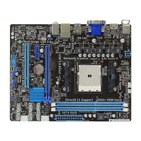
1.3.3 Motherboard layout 18.8cm(7.4in) CPU_FAN CHA_FAN KBMS DIGI ATX12V +VRM HDMI USB3_12 LAN_USB12 AUDIO A85XM-A PCIEX16 8111F ® BATTERY PCIEX1_1 A85X SATA6G_5 SATA6G_6 SATA6G_3 SATA6G_4 Super PCI1 SB_PWR 64Mb BIOS SPDIF_OUT USB3_34 USB56 USB34 SATA6G_1 SATA6G_2 SPEAKER AAFP F_PANEL Chapter 1: Product introduction... -
Page 19: Layout Contents
Ensure that you use an APU designed for the FM2 socket. The APU fits in only one correct orientation. DO NOT force the APU into the socket to prevent bending the pins and damaging the APU! A85XM-A A85XM-A CPU socket FM2 ASUS A85XM-A... -
Page 20: Apu Installation
1.4.1 APU installation Chapter 1: Product introduction... -
Page 21: Apu Heatsink And Fan Assembly Installation
1.4.2 APU heatsink and fan assembly installation Apply the Thermal Interface Material to the APU heatsink and APU before you install the heatsink and fan if necessary. To install the APU heatsink and fan assembly ASUS A85XM-A... - Page 22 To uninstall the APU heatsink and fan assembly Chapter 1: Product introduction 1-10...
-
Page 23: System Memory
DDR2 DIMM socket. DDR3 modules are developed for better performance with less power consumption. The figure illustrates the location of the DDR3 DIMM sockets: Channel Sockets Channel A DIMM_A1 A85XM-A Channel B DIMM_B1 A85XM-A 240-pin DDR3 DIMM sockets ASUS A85XM-A 1-11... -
Page 24: Memory Configurations
• The maximum 32GB memory capacity can be supported with 16GB or above DIMMs. ASUS will update the memory QVL once the DIMMs are available in the market. • The default memory operation frequency is dependent on its Serial Presence Detect (SPD), which is the standard way of accessing information from a memory module. - Page 25 1.35V-1.5V • • 11-28 Asint SLZ3128M8-EGJ1D(XMP) DS Asint 3128M8-GJ1D 9-9-9-24 1.6V • • Asint SLA302G08-EGG1C(XMP) DS Asint 302G08-GG1C 1.6V/1.6V • • Asint SLA302G08-EGJ1C(XMP) DS Asint 302G08-GJ1C 1.6V • • Elixir M2X8G64CB8HB5N-DG(XMP) DS Elixir 1213 N2CB4G8BOBN-DG • • ASUS A85XM-A 1-13...
- Page 26 DDR3 1333 MHz capability DIMM socket support Vendors Part No. Size Chip Brand Chip NO. Timing Voltage (Optional) 1 DIMM 2 DIMMs A-DATA AD3U1333C2G9 SS A-DATA 3CCD-1509HNA1126L 1.5V • • A-DATA AM2U139C2P1 SS ADATA 3CCD-1509A EL1127T • • A-DATA AX3U1333C2G9-BP SS - •...
-
Page 27: Channel Memory Configuration
1 DIMM: Supports one module inserted into any slot as Single-channel memory configuration. • 2 DIMMs: Supports two modules inserted into both the blue slots as one pair of Dual- channel memory configuration. Visit the ASUS website at www.asus.com for the latest QVL. ASUS A85XM-A 1-15... -
Page 28: Installing A Dimm
1.5.3 Installing a DIMM To remove a DIMM Chapter 1: Product introduction 1-16... -
Page 29: Expansion Slots
This motherboard supports PCI Express x1 network cards, SCSI cards, and other cards that comply with the PCI Express specifications. 1.6.5 PCI Express x16 slot This motherboard supports a PCI Express x16 graphics card that complies with the PCI Express specifications. ASUS A85XM-A 1-17... -
Page 30: Irq Assignments For This Motherboard
IRQ assignments for this motherboard PCIEx16_1 – – shared – – – – – PCIEx1_1 shared – – – – – – – PCI1 slot – – – – shared – – – Realtek LAN controller – shared – – –... -
Page 31: Jumpers
Normal Clear RTC (Default) A85XM-A Clear RTC RAM Turn OFF the computer and unplug the power cord. Move the jumper cap from pins 1-2 (default) to pins 2-3. Keep the cap on pins 2-3 for about 5~10 seconds, then move the cap back to pins 1-2. - Page 32 DRAM in slow refresh, power supply in reduced power mode). USBPWF A85XM-A +5VSB (Default) A85XM-A USB device wake-up • The USB device wake-up feature requires a power supply that can provide 500mA on the +5VSB lead for each USB port; otherwise, the system would not power up. •...
-
Page 33: Connectors
Rear Speaker Out Rear Speaker Out Rear Speaker Out Lime (Rear panel) Line Out Front Speaker Out Front Speaker Out Front Speaker Out Pink (Rear panel) Mic In Mic In Bass/Center Bass/Center Lime (Front panel) — — — Side Speaker Out ASUS A85XM-A 1-21... - Page 34 To configure an 8-channel audio output: Use a chassis with HD audio module in the front panel to support an 8-channel audio output. USB 2.0 ports 1 and 2. These two 4-pin Universal Serial Bus (USB) ports are for USB 2.0/1.1 devices.
-
Page 35: Internal Connectors
These are not jumpers! DO NOT place jumper caps on the fan connectors. • The CPU_FAN connector supports a CPU fan of maximum 2A (24 W) fan power. • Only the CPU_FAN connector support the ASUS Fan Xpert feature. ASUS A85XM-A 1-23... - Page 36 The system may become unstable or may not boot up if the power is inadequate. • If you are uncertain about the minimum power supply requirement for your system, refer to the Recommended Power Supply Wattage Calculator at http://support.asus. com/PowerSupplyCalculator/PSCalculator.aspx?SLanguage=en-us for details. Chapter 1: Product introduction 1-24...
- Page 37 RSATA_TXN7 RSATA_RXN7 RSATA_RXP7 A85XM-A SATA 6.0Gb/s connectors • These connectors are set to AHCI mode by default. If you intend to create a Serial ATA RAID set using these connectors, set the type of the SATA connectors in the BIOS to [RAID].
-
Page 38: System Panel Connector
PWR_BTN PIN 1 A85XM-A +HDD_LED- RESET A85XM-A System panel connector • System power LED (2-pin PLED) This 2-pin connector is for the system power LED. Connect the chassis power LED cable to this connector. The system power LED lights up when you turn on the system power, and blinks when the system is in sleep mode. -
Page 39: Digital Audio Connector
A85XM-A HD-audio-compliant Legacy AC’97 pin definition compliant definition A85XM-A Front panel audio connector • We recommend that you connect a high-definition front panel audio module to this connector to avail of the motherboard high-definition audio capability. • If you want to connect a high definition front panel audio module to this connector, set the Front Panel Type item in the BIOS to [HD]. - Page 40 USB-chargeable devices, optimized power efficiency and backward compatibility with USB 2.0. USB3_34 PIN 1 A85XM-A A85XM-A USB3.0 Front panel connector You can connect the ASUS front panel USB 3.0 bracket to this connector to obtain the front panel USB 3.0 solution. Chapter 1: Product introduction 1-28...
-
Page 41: Software Support
The contents of the Support DVD are subject to change at any time without notice. Visit the ASUS website at www.asus.com for updates. To run the Support DVD Place the Support DVD into the optical drive. - Page 42 Chapter 1: Product introduction 1-30...
-
Page 43: Chapter 2: Bios Information
BIOS in the future. Copy the original motherboard BIOS using the ASUS Update utility. 2.1.1 ASUS Update utility The ASUS Update is a utility that allows you to manage, save, and update the motherboard BIOS in Windows environment. ®... -
Page 44: Asus Ez Flash 2
Follow the onscreen instructions to complete the updating process. 2.1.2 ASUS EZ Flash 2 The ASUS EZ Flash 2 feature allows you to update the BIOS without using an OS-based utility. Before you start using this utility, download the latest BIOS file from the ASUS website at www.asus.com. -
Page 45: Asus Crashfree Bios 3 Utility
2.1.3 ASUS CrashFree BIOS 3 utility The ASUS CrashFree BIOS 3 is an auto recovery tool that allows you to restore the BIOS file when it fails or gets corrupted during the updating process. You can restore a corrupted BIOS file using the motherboard support DVD or a USB flash drive that contains the updated BIOS file. -
Page 46: Asus Bios Updater
2.1.4 ASUS BIOS Updater ASUS BIOS Updater allows you to update BIOS in DOS environment. This utility also allows you to copy the current BIOS file that you can use as a backup when the BIOS fails or gets corrupted during the updating process. -
Page 47: Updating The Bios File
Ensure to load the BIOS default settings to ensure system compatibility and stability. Select the Load Optimized Defaults item under the Exit menu. Refer to section 2.9 Exit menu for details. • Ensure to connect all SATA hard disk drives after updating the BIOS file if you have disconnected them. ASUS A85XM-A... -
Page 48: Bios Setup Program
BIOS setup program Use the BIOS Setup program to update the BIOS or configure its parameters. The BIOS screens include navigation keys and brief online help to guide you in using the BIOS Setup program. Entering BIOS Setup at startup To enter BIOS Setup at startup: •... - Page 49 Displays the Advanced mode menus • The boot device options vary depending on the devices you installed to the system. The Boot Menu(F8) button is available only when the boot device is installed to the • system. ASUS A85XM-A...
-
Page 50: Advanced Mode
The Advanced Mode provides advanced options for experienced end-users to configure the BIOS settings. The figure below shows an example of the Advanced Mode. Refer to the following sections for the detailed configurations. To access the EZ Mode, click Exit, then select ASUS EZ Mode. Menu items Menu bar... -
Page 51: Menu Items
You cannot select an item that is not user- configurable. A configurable field is highlighted when selected. To change the value of a field, select it and press <Enter> or click on it to display a list of options. ASUS A85XM-A... -
Page 52: Main Menu
Main menu The Main menu screen appears when you enter the Advanced Mode of the BIOS Setup program. The Main menu provides you an overview of the basic system information, and allows you to set the system date, time, language, and security settings. 2.3.1 System Language [English] Allows you to choose the BIOS language version from the options. -
Page 53: Administrator Password
To clear the user password, follow the same steps as in changing a user password, but press <Enter> when prompted to create/confirm the password. After you clear the password, the User Password item on top of the screen shows Not Installed. ASUS A85XM-A 2-11... -
Page 54: Ai Tweaker Menu
Ai Tweaker menu The Ai Tweaker menu items allow you to configure overclocking-related items. Be cautious when changing the settings of the Ai Tweaker menu items. Incorrect field values can cause the system to malfunction. The configuration options for this section vary depending on the CPU and DIMM model you installed on the motherboard. -
Page 55: Ai Overclock Tuner [Auto]
This item appears only when The EPU Power Saving Mode is set to [Enabled] and allows you to set power saving mode. Configuration options: [Auto] [Light Power Saving Mode] [Medium Power Saving Mode] [Max Power Saving Mode] ASUS A85XM-A 2-13... -
Page 56: Dram Timing Control
2.4.6 DRAM Timing Control The sub-items in this menu allow you to set the DRAM timing control features. Use the <+> and <-> keys to adjust the value. To restore the default setting, type [auto] using the keyboard and press <Enter>. Changing the values in this menu may cause the system to become unstable! If this happens, revert to the default settings. -
Page 57: Digi+ Vrm
Reducing phase number under light system loading to increase VRM efficiency. [Standard] Proceeds phase control depending on the CPU loading. [Optimized] Loads the ASUS optimized phase tuning profile. [Extreme] Proceeds the full phase mode. [Manual Adjustment] Allows manual adjustment. - Page 58 CPU Power Duty Control [T.Probe] [T.Probe] Maintains the VRM thermal balance. [Extreme] Maintains the VRM current balance. Do not remove the thermal module while changing the DIGI+VRM related parameters. The thermal conditions should be monitored. 2-16 Chapter 2: BIOS information...
-
Page 59: Advanced Menu
Disables the CPB (Core Performance Boost) mode or set it to [Auto] for automatic configuration. Configuration options: [Disabled] [Auto] C6 Mode [Enabled] Enables or disables C6 mode. Configuration options: [Enabled] [Disabled] IOMMU [Disabled] Set this item to [Enabled] to show IOMMU Mode. Configuration options: [Enabled] [Disabled] ASUS A85XM-A 2-17... -
Page 60: Sata Configuration
Bank Interleaving [Enabled] Enables or disables the bank memory interleaving. Configuration options: [Enabled] [Disabled] Channel Interleaving [Enabled] Enables or disables the channel memory interleaving. Configuration options: [Enabled] [Disabled] Core Leveling Mode [Automatic mode] Allows you to change the number of working Compute Unit on the system. Configuration options: [Automatic mode] [One core per processor] [One Compute Unit] [One core per Compute Unit] 2.5.2... -
Page 61: Usb Configuration
® LucidLogix Virtu MVP technologies. Primary Video Device [PCIE / PCI Video] Selects the primary display device. Configuration options: [IGFX Video] [PCIE / PCI Video] Integrated Graphics [Auto] Enables the integrated graphics controller. Configuration options: [Auto] [Force] ASUS A85XM-A 2-19... -
Page 62: Onboard Devices Configuration
UMA Frame Buffer Size [Auto] This item appears only when you set the previous item to [Force]. Configuration options: [Auto] [32M] [64M] [128M] [256M] [512M] [1G] [2G] 2.5.5 Onboard Devices Configuration HD Audio Device [Enabled] [Enabled] Enables the High Definition Audio Controller. [Disabled] Disables the controller. -
Page 63: Network Stack
This item allows user to disable or enable the Ipv4 PXE Boot support. Configuration options: [Disabled] [Enable] Ipv6 PXE Support [Enabled] This item allows user to disable or enable the Ipv6 PXE Boot support. Configuration options: [Disabled] [Enable] ASUS A85XM-A 2-21... -
Page 64: Monitor Menu
Monitor menu The Monitor menu displays the system temperature/power status, and allows you to change the fan settings. 2.6.1 CPU Temperature / MB Temperature [xxxºC/xxxºF] The onboard hardware monitor automatically detects and displays the CPU and motherboard temperatures. Select Ignore if you do not wish to display the detected temperatures. 2.6.2 CPU / Chassis Fan Speed [xxxx RPM] or [Ignore] / [N/A]... -
Page 65: Anti Surge Support [Auto]
0% to 100%. When the CPU temperature is under the lower limit, the CPU fan will operate at the minimum duty cycle. 2.6.5 Anti Surge Support [Auto] This item allows you to enable or disable the Anti Surge function. Configuration options: [Auto] [Disabled] [Enabled] ASUS A85XM-A 2-23... -
Page 66: Boot Menu
Boot menu The Boot menu items allow you to change the system boot options. Scroll down to display the following items: 2-24 Chapter 2: BIOS information... -
Page 67: Fast Boot [Enabled]
Accelerates the boot speed on the next boot after AC power loss. 2.7.2 Full Screen Logo [Enabled] [Enabled] Enables the full screen logo display feature. [Disabled] Disables the full screen logo display feature. Set this item to [Enabled] to use the ASUS MyLogo 2™ feature. ASUS A85XM-A 2-25... -
Page 68: Bootup Numlock State [On]
POST Delay Time [3 sec] This item appears only when you set Full Screen Logo to [Enabled]. This item allows you to select the desired additional POST waiting time to easily enter the BIOS setup. You can only execute the POST delay time during Normal Boot. The values range from 0 to 10 seconds. This feature will only work under normal boot. -
Page 69: Security Boot
Allows you to immediately load the default Security Boot keys, Platform key (PK), Key-exchange Key (KEK), Signature database (db), and Revoked Signatures (dbx). The Platform Key (PK) state will change from Unloaded mode to Loaded mode. The settings are applied after reboot or at the next reboot. ASUS A85XM-A 2-27... - Page 70 Key-exchange Key (KEK) refers to Microsoft Secure Boot Key Enrollment Key (KEK). ® Clear Secure Boot keys This item appears only when you load the default Secure Boot keys. This item allows you to clear all default Secure Boot keys. PK Management The Platform Key (PK) locks and secures the firmware from any non-permissible changes.
-
Page 71: Boot Option Priorities
• To select the boot device during system startup, press <F8> when ASUS Logo appears. • To access Windows OS in Safe Mode, press <F8> after POST. -
Page 72: Boot Override
2.7.11 Boot Override These items displays the available devices. The number of device items that appears on the screen depends on the number of devices installed in the system. Click an item to start booting from the selected device. 2-30 Chapter 2: BIOS information... -
Page 73: Tools Menu
<Enter> to display the submenu. 2.8.1 ASUS EZ Flash 2 Utility Allows you to run ASUS EZ Flash 2. Press [Enter] to launch the ASUS EZ Flash 2 screen. For more details, see section 2.1.2 ASUS EZ Flash 2. 2.8.2... -
Page 74: Exit Menu
When you select this option or if you press <Esc>, a confirmation window appears. Select Yes to discard changes and exit. . ASUS EZ Mode This option allows you to enter the EZ Mode screen. Launch EFI Shell from filesystem device This option allows you to attempt to launch the UEFI Shell application (shellx64.efi) from one... -
Page 75: Appendices
Cet appareil est conforme aux normes CNR exemptes de licence d’Industrie Canada. Le fonctionnement est soumis aux deux conditions suivantes : (1) cet appareil ne doit pas provoquer d’interférences et (2) cet appareil doit accepter toute interférence, y compris celles susceptibles de provoquer un fonctionnement non souhaité de l’appareil. ASUS A85XM-A... -
Page 76: Canadian Department Of Communications Statement
ASUS Recycling/Takeback Services ASUS recycling and takeback programs come from our commitment to the highest standards for protecting our environment. We believe in providing solutions for you to be able to responsibly recycle our products, batteries, other components as well as the packaging materials. -
Page 77: Asus Contact Information
+1-812-282-3777 +1-510-608-4555 Web site usa.asus.com Technical Support Telephone +1-812-282-2787 Support fax +1-812-284-0883 Online support support.asus.com ASUS COMPUTER GmbH (Germany and Austria) Address Harkort Str. 21-23, D-40880 Ratingen, Germany +49-2102-959911 Web site www.asus.de Online contact www.asus.de/sales Technical Support Telephone +49-1805-010923* Support Fax... - Page 78 Appendices...
Need help?
Do you have a question about the A85XM-A and is the answer not in the manual?
Questions and answers