Table of Contents
Advertisement
Quick Links
H-IM-SCU-LT
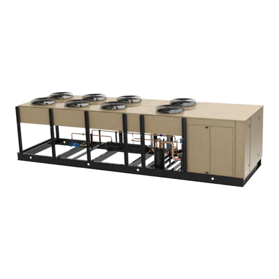
Screw Compressor Condensing Units
Table of Contents
General Safety Information . . . . . . . . . . . . . . . . . . . 2
Inspection . . . . . . . . . . . . . . . . . . . . . . . . . . . . . . . . 2
Warranty Statement . . . . . . . . . . . . . . . . . . . . . . . . 2
Space and Location Requirements . . . . . . . . . . . . . 3
Condensing Unit Rigging and Mounting . . . . . . . . . 4
Head Pressure Control . . . . . . . . . . . . . . . . . . . . . . 5
Refrigerant Oil Type . . . . . . . . . . . . . . . . . . . . . . . . 5
Recommended Refrigerant Piping Practices . . . . . 7
Refrigerant Pipe Support . . . . . . . . . . . . . . . . . . . . 7
Suction Lines . . . . . . . . . . . . . . . . . . . . . . . . . . . . . 7
Liquid Lines . . . . . . . . . . . . . . . . . . . . . . . . . . . . . . 8
Unit Cooler Piping . . . . . . . . . . . . . . . . . . . . . . . . . . 8
October 2017
Low Temperature Models
Installation and
Operations Manual
Line Sizing . . . . . . . . . . . . . . . . . . . . . . . . . . . . 9-12
Evacuation and Leak Detection . . . . . . . . . . . . . . 12
Refrigerant Charging Instructions . . . . . . . . . . . . 12
Field Wiring . . . . . . . . . . . . . . . . . . . . . . . . . . . . . . 12
C450 System Control & Adjustment . . . . . . . . 13-14
Check Out and Start Up . . . . . . . . . . . . . . . . . . . . 15
Operational Check Out . . . . . . . . . . . . . . . . . . . . . 15
System Balancing - Compressor Superheat . . . . . 16
System Troubleshooting Guide . . . . . . . . . . . . . . . 18
Preventive Maintenance Guidelines . . . . . . . . . . . 18
Wiring Diagrams . . . . . . . . . . . . . . . . . . . . . . . 19-26
Interlink™ Replacement Parts . . . . . . . . . . . . . . . 30
Part No. 25008401
Advertisement
Table of Contents

Subscribe to Our Youtube Channel
Related Manuals for Heatcraft H-IM-SCU-LT


Summary of Contents for Heatcraft H-IM-SCU-LT
-
Page 1: Table Of Contents
Installation and Operations Manual H-IM-SCU-LT October 2017 Part No. 25008401 Screw Compressor Condensing Units Low Temperature Models Table of Contents General Safety Information . . . . . . . . . . . . . . . . . . . 2 Line Sizing . -
Page 2: General Safety Information
SSV and DSV condensing units are designed for operation with DX evaporators only, and is not designed to beapplied with flooded or liquid recirculating evaporators. Applications of Heatcraft SSV and DSV Screw condensing units with evaporators that are not DX are not the responsibility of, and will not be supported by Heatcraft Refrigeration Products. -
Page 3: Space And Location Requirements
Fences must have 50% free area, with 1 foot undercut, a “W” minimum clear- ance, and must not exceed the top ofunit. If these requirements are not met, unit must be installed as indicated for “Units in Pits". © 2017 Heatcraft Refrigeration Products, LLC... -
Page 4: Condensing Unit Rigging And Mounting
(see section above, "Location And Mounting" for mounting instructions). equipment for maintenance or repair. © 2017 Heatcraft Refrigeration Products, LLC... -
Page 5: Head Pressure Control
CR2 = ON CR2 = ON CR2 = OFF HSN-74 CR1 = ON CR1 = ON CR1 = OFF CR2 = ON CR2 = OFF CR2 = OFF NOTE: Mechanical subcooler/economizer not energized during 50% operation © 2017 Heatcraft Refrigeration Products, LLC... - Page 6 • Discharge gas temperature (PTC) • Rotating direction / phase sequence • Cable breakage in the PTC sensor circuit • Monitoring phase failure / phase asymmetry • Limits number of motor starts. Oil-Cooler Arrangement © 2017 Heatcraft Refrigeration Products, LLC...
-
Page 7: Recommended Refrigerant Piping Practices
3. Piping attached to a vibrating object (such as a compressor or The system as supplied by Heatcraft Refrigeration Products, was thoroughly cleaned compressor base) must be supported in such a manner that will not and dehydrated at the factory. -
Page 8: Liquid Lines
• (6) 90° elbows in main line plus a 90° turn through a tee. line to both evaporators. • (5) addtional 90° elbows to first evaporator. • (4) additional 90° elbows to second evaporator. © 2017 Heatcraft Refrigeration Products, LLC... -
Page 9: Line Sizing
12.8 17.0 21.3 31.9 10.1 42.5 13.5 R-448A,R-449A 10.9 13.0 17.4 21.7 32.6 43.5 10.9 R-507, R-404A 10.2 12.2 16.3 20.4 30.6 40.8 11.8 NOTES: Based on 110˚F liquid temperature at bottom of riser. © 2017 Heatcraft Refrigeration Products, LLC... - Page 10 2. Suction line sizes selected at pressure drop equivalent to 2˚F. Reduce estimate of system capacity accordingly. 3. If system load drops below 40% of design, consideration to installing double suction risers should be made. © 2017 Heatcraft Refrigeration Products, LLC...
- Page 11 2. Suction line sizes selected at pressure drop equivalent to 2˚F. Reduce estimate of system capacity accordingly. 3. If system load drops below 40% of design, consideration to installing double suction risers should be made. © 2017 Heatcraft Refrigeration Products, LLC...
-
Page 12: Evacuation And Leak Detection
A significant rise indicates a leak or moisture trapped in the system. Once satisfactory, raise the pressure to 2 psig with the refrigerant and remove the vacuum pump. © 2017 Heatcraft Refrigeration Products, LLC... -
Page 13: C450 System Control & Adjustment
In the Main (sensor status) screens, press LC2 terminals are only on up and down hold both and for 5 seconds control and expansion modules with two output access the setup Start screens. relays. © 2017 Heatcraft Refrigeration Products, LLC... - Page 14 Connected Sensor Specified Voltage Range Measured between a Sensor terminal (Sn1, Sn2, or Sn3) and a Common Terminal (C) A99B temperature Sensor 0.49 to 1.43 VDC P499 electronic Pressure Transducer 0 to 5.0 VDC © 2017 Heatcraft Refrigeration Products, LLC...
-
Page 15: Check Out And Start Up
Activating the oil separator heater 24 hours prior to start-up is required. © 2017 Heatcraft Refrigeration Products, LLC... -
Page 16: System Balancing - Compressor Superheat
The fan motors start running. 8. The system will now operate in the refrigeration cycle until another defrost period is initiated by the timer. Electric Defrost Troubleshooting The electric defrost units are relatively simple and trouble-free in operation: © 2017 Heatcraft Refrigeration Products, LLC... -
Page 17: System Troubleshooting Guide
Reduce charge. Oil temperature too high Suction superheat too high Adjust superheat at expansion valves so that it is within acceptable range. Dirty oil cooler coil Clean coil Fans not running Check electrical circuit © 2017 Heatcraft Refrigeration Products, LLC... -
Page 18: Preventive Maintenance Guidelines
• Check compressor sightglass (if equipped) for proper oil level. • Check condition of condenser. Look for accumulation of dirt and debris © 2017 Heatcraft Refrigeration Products, LLC... -
Page 19: Wiring Diagrams
Wiring Diagrams - Typical WITHOUT DEFROST - COMPRESSOR POWER WITHOUT DEFROST - CONDENSER/OIL COOLER FAN POWER © 2017 Heatcraft Refrigeration Products, LLC... - Page 20 Wiring Diagrams - Typical WITHOUT DEFROST - CONTROL POWER © 2017 Heatcraft Refrigeration Products, LLC...
- Page 21 Wiring Diagrams - Typical WITHOUT DEFROST - COMPRESSOR CIRCUIT © 2017 Heatcraft Refrigeration Products, LLC...
- Page 22 Wiring Diagrams - Typical WITH DEFROST - COMPRESSOR POWER WIRING WITH DEFROST - CONDENSER/OIL COOLER FAN POWER © 2017 Heatcraft Refrigeration Products, LLC...
- Page 23 Wiring Diagrams - Typical WITH DEFROST - EVAPORATOR/DEFROST HEATER POWER © 2017 Heatcraft Refrigeration Products, LLC...
- Page 24 Wiring Diagrams - Typical WITH DEFROST - CONTROL POWER © 2017 Heatcraft Refrigeration Products, LLC...
- Page 25 Wiring Diagrams- Typical WITH DEFROST - COMPRESSOR CIRCUIT © 2017 Heatcraft Refrigeration Products, LLC...
- Page 26 Wiring Diagrams - Typical WITH DEFROST - DEFROST CONTROL © 2017 Heatcraft Refrigeration Products, LLC...
- Page 27 Notes: © 2017 Heatcraft Refrigeration Products, LLC...
- Page 28 Notes: © 2017 Heatcraft Refrigeration Products, LLC...
- Page 29 Notes: © 2017 Heatcraft Refrigeration Products, LLC...
-
Page 30: Interlink™ Replacement Parts
The original invoice from the parts supplier must accompany all warranty claims for replacement part reimbursement. Heatcraft Refrigeration Products reserves the right to adjust the compensation amount paid on any parts submitted for warranty reimbursement when a parts supplier's original invoice is not provided with a claim.
Need help?
Do you have a question about the H-IM-SCU-LT and is the answer not in the manual?
Questions and answers