Table of Contents
Advertisement
H-IM-67H
Replaces H-IM-67H (01/18)
Installation and Operation Manual
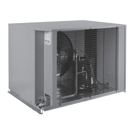
MAC
Condensing Units
March 2018
T
General safety and inspection
Condensing unit specifications ............................... 2
Evaporator unit specifications ................................. 3
Evaporator placement ............................................. 4
Condensing Unit placement.....................................5
Refrigerant piping and line sizes ..........................6-8
Leak detection and evacuation ................................ 9
Field wiring ........................................................... 10
Installation .......................................................... 11
Wiring ................................................................ 12
Box temp control settings
Start-up operation ............................................... 13
Operating mode display ..................................... 14
Program & review settings/changes ..............15-18
Low ambient operation
Pumpdown ....................................................19-20
Defrost ................................................................ 20
Alarms and error indicator LED ........................ 21
Space sensor terminal
Checking sensors ............................................... 22
Control sensor and piping .................................. 23
Exp. valve motor winding resistance ................. 24
Smart Controller ............................................25-36
Operational checkout ......................................... 37
Preventive maintenance ................................38-40
Diagnostics .......................................................41-44
Beacon II parts lists ..........................................45-46
Startup Checklist ..............................................47-48
Wiring diagrams ...............................................49-51
Warranty information ............................................ 52
Series
Part #25006401
C
ABLE of
ONTENTS
Advertisement
Table of Contents

Related Manuals for Heatcraft BOHN MAC Series


Summary of Contents for Heatcraft BOHN MAC Series
-
Page 1: Table Of Contents
Series Condensing Units H-IM-67H March 2018 Part #25006401 Replaces H-IM-67H (01/18) Installation and Operation Manual ABLE of ONTENTS General safety and inspection Condensing unit specifications ....... 2 Evaporator unit specifications ......... 3 Evaporator placement ..........4 Condensing Unit placement........5 Refrigerant piping and line sizes ......6-8 Leak detection and evacuation ........ -
Page 2: Condensing Unit Specifications
General Safety Information General Safety Information 1. Installation and maintenance to be performed only 3. Avoid contact with sharp edges and coil surfaces, by certified personnel who are familiar with this they are a potential injury hazard. type of equipment. 4. -
Page 3: Evaporator Unit Specifications
12,000 61.5 49.25 11.7 LET160BEB2N6MK Freezer 16,000 77.5 65.25 1-1/8 15.7 ADT104BEB2N6MK Cooler 10,400 45.5 33.25 ― MAC8X LET160BEB2N6MK Freezer 16,000 77.5 65.25 1-1/8 15.7 LET180BEB2N6MK Freezer 18,000 77.5 65.25 1-1/8 15.7 Figure 2. © 2018 Heatcraft Refrigeration Products LLC... -
Page 4: Evaporator Placement
Evaporator Placement Figure 3. Evaporator Placement In Cooler/Freezer Loading Door Loading Door Freezer Freezer Cooler Cooler Note: Whenever possible always try to position the evaporator to blow towards the walk-in door. Never position the evaporator over or adjacent to a door opening. Evaporator Minimum Unit Clearance 1 1/2 H 1 1/2 H... -
Page 5: Condensing Unit Placement
Condensing Unit Placement Space and Location Requirements unit should be mounted away from noise sensitive spaces The most important consideration which must be taken and must have adequate support to avoid vibration and into account when deciding upon the location of air- noise transmission into the building. -
Page 6: Refrigerant Piping And Line Sizes
Refrigeration Piping And Line Sizing Refrigeration Piping And Line Sizing The system as supplied by Bohn/Heatcraft, was thoroughly national codes and in conformance with good practice required cleaned and dehydrated at the factory. Foreign matter may enter for the proper operation of the system. The interconnecting pipe the system by way of the evaporator to condensing unit piping. - Page 7 Refrigeration Piping Condensate Drain Lines Suction Lines Copper drain lines should be used and properly protected Note: If the suction line must rise to the point higher from freezing. In running drain lines, provide a minimum than the suction connection on the evaporator, a suction of 1/4 inch per foot pitch for proper drainage.
- Page 8 Refrigeration Piping Figure 7. Example of Pipe Support 3. Piping attached to a vibrating object (such as a compressor or compressor base) must be supported in such a manner that will not restrict the movement of the vibrating object. Rigid mounting will fatigue the copper tubing.
-
Page 9: Leak Detection And Evacuation
Leak Detection And Evacuation Leak Detection A shut-off valve between the gauge connection and After all lines are connected, the entire system must be vacuum pump should be provided to allow the system leak tested. The complete system should be pressurized pressure to be checked after evacuation. -
Page 10: Field Wiring
Field Wiring WARNING: All wiring must be done in accordance with applicable codes and local ordinances. The field wiring should enter the areas as provided on the characteristic for wiring the unit. unit. The wiring diagram for each unit is located on the Consult the wiring diagram in the unit cooler and in the inside of the electrical panel door. -
Page 11: Beacon Ii Controller
Beacon II Controller Condensing Unit Installation Tips Use a minimum 18 gauge wire for all low voltage The condensing unit control panel contains the relays, connections. contactors, and a terminal block which is appropriately marked to match the low voltage wiring connections. •... -
Page 12: Refrigerant Line Brazing
Beacon II Controller Refrigerant Line Brazing (CAUTION) The electric expansion valve and the suction temperature sensor on the suction line are factory installed. Care must All 24 volt wiring must be run separate from the line be taken when brazing these lines at the evaporator. voltage wiring. -
Page 13: Refrigerant Charging
Beacon II Controller Box Temperature Control Settings • There is an on board room thermostat on the minimum 4-minute “OFF” time. This means Beacon II board which can be adjusted to the that the system will run in the cooling mode desired room temperature. -
Page 14: Initial Power On
Beacon II Controller Initial Power On At the initial application of power to the system, the the compressor ran for at least 2 minutes, the EEV will compressor and the evaporator fans will be in a 4 minute close and the compressor will pumpdown and shut off. hold-off cycle and will not start immediately. -
Page 15: Program & Review Settings/Changes
Beacon II Controller Programming And Reviewing Note: If Smart Controller is in use, do not Settings/Changes program the board-- go to pg. 31 to program Programming & Reviewing Smart Controller. The Program Review button is used to program, review and change all program settings for the system. Programming And Reviewing Settings/Changes “PROGRAM REVIEW”... - Page 16 Demand Defrost Enable – “ddF” – Demand defrost is Demand Defrost Enable – “ddF” – Demand defrost is • the LED display of the Heatcraft Quick Response Controller • the LED display of the Heatcraft Quick Response Controller available for electric defrost systems only. Selection is board.
- Page 17 Beacon II Controller Programming & Reviewing Use this button to “FORCE DEFROST”. To force a defrost, press the “FORCE DEFROST” button. The system will pumpdown. The heaters MONITOR MONITOR are then turned on. The display will show “dEF” and room temp. FORCE FORCE DEFROST...
- Page 18 Beacon II Controller Programming And Reviewing Settings/Changes (continued) Use this button to “CLEAR/TEST” Pressing this button ONCE will return the LED display to the default display. With the system in the OFF mode, pressing and holding this button will start the “TEST” mode.
-
Page 19: Pumpdown
Beacon II Controller Status Indicator LED (continued) Status LED Display Description • ERRORS Room temperature sensor shorted, open or not installed Defrost temperature sensor shorted, open or not installed Suction temperature sensor shorted, open or not installed Suction pressure transducer shorted, open or not installed Outdoor temperature sensor shorted Low superheat during cooling... -
Page 20: Defrost
Beacon II Controller Service Mode Beacon II does not have a real time clock but it keeps track of the time that has elapsed in its memory. It also keeps A SPST switch (S1 & S2) is supplied, for each system, in memory the number of defrosts scheduled and how in the condensing unit for shutting off the system. -
Page 21: Alarms And Error Indicator Led
Beacon II Controller Alarms Beacon II provides a set of dry contacts for use in value for the Alarm time ALt, programmed. signaling an alarm. These contacts can be connected to • System Start-Up Failure – LED Display: A3 – a light, a buzzer, a bell, etc., (not to exceed 115 volts Compressor pumps down and tries to restart after four and 2 amps) which will be activated when an alarm... -
Page 22: Evaporator Fans Shut Down By Operators
Beacon II Controller Evaporator Fans Shut Down By Sensors on the Beacon II system, as supplied, will not Operators simulate product temperature. In some installations, it is desirable to shut off the This input can be monitored on the LED display by using the “MONITOR”... -
Page 23: System Defaults
Beacon II Controller System Defaults Table 6. System Defaults Refrigerant R-404A R-404A REFTYP Box Temperature -10F BOXTMP Superheat SUPRHT Smart Defrost SMTDEF Demand Defrost DMDDFT Defrost Start Times 9am/9pm 3am, 6am, 9am, 12pm, 3pm, 6pm, 9pm, 12pm DET ST Defrost Fail-Safe Times 40 min. -
Page 24: Checking Operation Of Exp. Valve Exp. Valve Motor Winding Resistance
Beacon II Controller Checking Operation Of Expansion Valve (EEV) This can also be checked by using the EXV test pins on 1. To check if the expansion valve is closing properly; the board. This is indicated by a 0 to 5 Volts DC signal. At 0 Volts the valve is closed and at 5 Volts the valve is Install a pressure gauge-set to suction line at the condensing fully open. - Page 25 Beacon II Smart Controller The Smart Controller performs all of the your refrigeration system. The Smart Controller standard Beacon functions with the additional will display the problem in addition to letting benefit of remote monitoring. The Smart you know when to call for service. See pages Controller is mounted in the manager’s office 49-51 for proper wiring instructions.
- Page 26 ) Remote mounting for easy access MONITOR, ENTER, CLEAR, SETPOINT AND b ) Remote monitoring and programming TIME. through integration with Heatcraft RRC (Remote Refrigeration Control). Visit The normal LCD display will show the www.heatcraftrpd.com for more Programmed Box Set-point temperature. Actual information.
- Page 27 Beacon II Smart Controller Features • Monitoring of the complete refrigeration • Can be mounted up to 1000 ft. away system. from the system being controlled. • Programming of a variety of • Each Beacon II Smart Controller can parameters for the optimum control of control four independent systems the refrigeration system.
- Page 28 Installation Installation The Smart Controller should be installed in a A terminal strip for wiring connections is located location where the large Liquid Crystal Display on the base of the Smart Controller. To access (LCD) can be viewed easily, yet is secure and this terminal strip, pull both halves of the Smart vibration free.
- Page 29 Wiring Wiring Power Supply All 24 volt wiring must be run separate from The Beacon II Smart Controller gets its 24 the line voltage wiring. VAC power supply from an evaporator. When controlling multiple systems, the Beacon The terminal strip in the Smart Controller II Smart Controller is powered from the is labeled similarly to that of the Beacon II evaporator of only one of the systems.
- Page 30 Initialization of Beacon II Smart Controller INITIALIZATION of BEACON II SMART CONTROLLER When power is first applied to the Beacon II After “WAIT” is displayed it may take up to 2 Smart Controller it checks the configuration of minutes for the initialization to be completed and the system to which it is connected and stores the normal LCD screen is displayed.
- Page 31 Programming Smart Controller PROGRAMMING SMART CONTROLLER Programming Beacon II Smart Controller To make a change, press the PROGRAM REVIEW button until – Defrost Fail Safe Time: 10 to 200 minutes. • the setpoint item that needs to be changed is displayed. The DEFSAF When this time has elapsed, the defrost cycle will end, SETPOINT Slide-bar is then used to change to the desired new...
- Page 32 Monitoring Smart Controller MONITORING SMART CONTROLLER The monitoring function can be used to monitor live system data. When multiple evaporators are connected as master/slave The information displayed, such as super-heat, is the actual depressing the + or - button will display information specific superheat of the system as it is changing.
- Page 33 Locking Beacon II Smart Controller LOCKING BEACON II SMART The error code will flash alternately with the CONTROLLER normal display information. When the error condition is corrected, the error code will BEACON II SMART CONTROLLER is no longer be displayed and only the normal lockable to prevent programmed settings to be information will be displayed.
- Page 34 Alarm Codes Alarm Codes The system will pumpdown, cycle off and try to restart for three consecutive times. Each try will • *BOXHI : Box temperature too high be after the 4 minutes “Hold Off” period, for the following fault conditions. •...
- Page 35 Smart Defrost Smart Defrost The Beacon II Smart Controller continuously monitors the system performance to determine the need for defrost. It uses a variety of data such as the outdoor ambient and box temperature in its decision making process. A defrost cycle will only be triggered at a programmed defrost time if the system determines a defrost is necessary.
-
Page 36: Smart Controller
Grounding Grounding The earth/chassis ground connections on the new Beacon II and Smart Controller are used for common-mode noise filtering and should be connected to a good chassis ground or earth ground for best noise immunity. - Beacon II Board - All four corner brass spacers on the Beacon II board should have sheet-metal screws and they should all be screwed in. -
Page 37: Operational Checkout
(d) The maximum approved settings for high pres- ant for proper operation. Do not overcharge. Re- sure controls on Bohn/Heatcraft air cooled con- member that bubbles in a sight glass may be caused densing equipment is 400 psig. On air cooled by a restriction as well as a shortage of refrigerant. -
Page 38: Preventive Maintenance
The following is Bohn/Heatcraft’s minimum recommendations... - Page 39 Preventive Maintenance...
- Page 40 Preventive Maintenance...
-
Page 41: Diagnostics
Diagnostics Beacon II Troubleshooting Guide PROBLEM Step ACTION ITEM IF OK IF NOT OK Check Primary Power Supply Disconnect 1. Check fuses and circuit breakers Check Voltage to Evaporator Transformer Go to 2. Check field wiring for breaks LED is not lit. Check Transformer Secondary Output Volts next step 3. - Page 42 Diagnostics Beacon II Troubleshooting Guide (continued) PROBLEM Step ACTION ITEM IF OK IF NOT OK Check wiring connection to the board • Correct field wiring to the board Low Pressure Safety (LPS) Tripped: • Check for correct refrigerant type • Change setpoint to match refrigerant •...
- Page 43 Diagnostics Beacon II Troubleshooting Guide (continued) PROBLEM Step ACTION ITEM IF OK IF NOT OK Multi-out to Multi-in Check for 24 volts power to the board 1. If no voltage, see “LED is not lit” above communication wiring for low voltage, see “88888 LED display” (only shows after initial Check for crossed communication wiring Go to...
- Page 44 Diagnostics Beacon II Troubleshooting Guide (continued) PROBLEM Step ACTION ITEM IF OK IF NOT OK Check system operation: Is it running? 1. Check power to condensing unit Check position of Service Mode switches Check compressor overloads and contactor Check system charge 2.
-
Page 45: Beacon Ii Parts Lists
Parts Table 7. Condensing Unit Parts List CONDENSING UNITS MAC7X MAC8X MAC5X PART DESCRIPTION Compressor - Freezer ZF15K4EZF13K4E ZF15K4E Compressor - Cooler RST43C1EZS13KAE ZS13KAE Disconnect Fuses 2251011322510112 22510113 Start Relay - Cooler 1007647 Start Capacitor - Cooler 7076959 Run Capacitor - Cooler 7076950 70757856 Compressor Contactor - Cooler... - Page 46 Beacon II Smart Controller Table 9. Beacon II Smart Controller Parts List PART PART DESCRIPTION NUMBER Beacon II Smart Controller 89704302 Table 10. Beacon II Operational Limits OPERATIONAL LIMITS Voltage 22 VAC to 30 VAC Controlling Box Temp. Range -30°F to 70°F Box Temp.
-
Page 47: Startup Checklist
Startup Checklist Date of Start-up COOLER Refrigerant Type R448A Store Address Box Setpoint Temp. 35°F. CONDENSING UNIT Superheat 8°F. MODEL # No. of Defrost/Day SERIAL # Defrost End Temp. 50°F. COOLER UNIT MODEL # SYSTEM CHECKS SERIAL # • Check compressor superheat for the FREEZER UNIT COOLER (Should be between 20°F. - Page 48 Startup Checklist RECORD OUTDOOR TEMPERATURE ______°F. SYSTEM VOLTAGE ______Volts ______PH ______Hz Cooler compressor amps ______L1 ______L2 ______L3 Freezer compressor amps ______L1 ______L2 ______L3 Cooler discharge pressure ______PSIG Freezer discharge pressure ______PSIG Cooler suction pressure ______PSIG Freezer suction pressure ______PSIG Cooler suction temperature ______°F.
-
Page 49: Wiring Diagrams
Wiring Diagrams Diagram 1. Low Profile Evaporator Wiring... - Page 50 Wiring Diagrams Diagram 2. MAC Unit Wiring...
- Page 51 Wiring Diagrams Diagram 3. 24 Volt Connection Wiring with Smart Controller Diagram 3. 24 Volt Connection Wiring With Smart Controller COOLER FREEZER...
-
Page 52: Warranty Information
Compressor Part - 5 Years Due to ongoing efforts in product improvement, specifications are subject to change without notice. A Brand of Heatcraft Refrigeration Products LLC 2175 West Park Place Blvd. • Stone Mountain, GA 30087 770.465.5600 • Fax: 770.465.5990...
Need help?
Do you have a question about the BOHN MAC Series and is the answer not in the manual?
Questions and answers