Table of Contents
Advertisement
Quick Links
installer:
leave this manual with the appliance.
consUMer:
retain this manual for future reference.
WarninG
Fire or eXplosion HaZarD
Failure to follow safety warnings exactly
could result in serious injury, death or
property damage.
— Do not store or use gasoline or other
flammable vapors and liquids in the
vicinity of this or any other appliance.
— WHat to Do iF YoU sMell Gas
•
Do not try to light any appliance.
•
Do not touch any electrical switch;
do not use any phone in your building.
•
Leave the building immediately.
•
Immediately call your gas supplier
from a neighbor's phone. Follow
the gas supplier's instructions.
•
If you cannot reach your gas
supplier, call the fire department.
— installation and service must be
performed by a qualified installer,
service agency or the gas supplier.
WARNING
NEVER
A barrier designed to reduce the risk of burns from the
hot viewing glass is provided with this appliance and shall
be installed for the protection of children and other at-risk
individuals.
installation instrUctions
anD oWner's ManUal
HOT GLASS
WILL
CAUSE BURNS.
DO NOT TOUCH
GLASS
UNTIL COOLED.
ALLOW CHILDREN
TO TOUCH GLASS.
Direct Vent
Zero clearance Gas
Fireplace MoDel series:
MUltiFUnction reMote (MF)
DVtl27Fp90(n,p)-1
WarninG
if not installed, operated and maintained
in accordance with the manufacturer's
instructions, this product could expose you
to substances in fuel or from fuel combustion
which can cause death or serious illness.
this appliance may be installed in an aftermarket,
permanently located, manufactured home (Usa
only) or mobile home, where not prohibited by
state or local codes.
this appliance is only for use with the type of
gas indicated on the rating plate. this appliance
is not convertible for use with other gases,
unless a certified kit is used.
GAS-FIRED
Ul File no.
MH45034
Page 1
Advertisement
Table of Contents

Related Manuals for Empire Comfort Systems White Mountain Hearth DVTL27FP90N-1


Summary of Contents for Empire Comfort Systems White Mountain Hearth DVTL27FP90N-1
- Page 1 installation instrUctions anD oWner’s ManUal Direct Vent installer: Zero clearance Gas leave this manual with the appliance. consUMer: Fireplace MoDel series: retain this manual for future reference. MUltiFUnction reMote (MF) DVtl27Fp90(n,p)-1 WarninG Fire or eXplosion HaZarD Failure to follow safety warnings exactly could result in serious injury, death or GAS-FIRED property damage.
- Page 2 BeFore YoU start Gas Supply see page 12. Locating Fireplace see page 13. Electrical Considerations see page 14. Installation see pages 15-19. 5. Vent System Identification see page 20. Venting Fireplace see pages 21-27. Framing and Finishing see pages 28-29. 8. Install Fiber Panels see page 30. Placing Glowing Embers see page 31 10. Log Placement see pages 32-41.
-
Page 3: Table Of Contents
taBle oF contents section paGe INTRODUCTION ....................................4 SPECIFICATIONS ....................................5 ACCESSORIES ....................................6 FIREPLACE DIMENSIONS ................................7 CLEARANCES....................................8-9 TERMINATION CLEARANCES ..............................10 VENT TERMINAL CLEARANCES ..............................11 GAS SUPPLY ....................................12-13 LOCATING FIREPLACE .................................13 ELECTRICAL CONSIDERATIONS ..............................14 INSTALLATION ..................................15-19 VENT SYSTEM IDENTIFICATION ..............................20 VENTING FIREPLACE ................................20-22 TOP VENT - HORIZONTAL TERMINATION ...........................23 TOP VENT - VERTICAL TERMINATION ............................24 VERTICAL TERMINATION ................................25-27... -
Page 4: Introduction
This fireplace is design certified in accordance with American level. However, if the heating value of the gas has been reduced, National Standard ANSI Z21.50 and by Underwriters Laboratories this general rule may not apply. Check with Empire Comfort Systems as a Direct Vent Gas Fireplace and shall be installed according to for proper orifice size identification. these instructions. -
Page 5: Specifications
speciFications DVtl27Fp92n DVtl27Fp92p natural Gas propane Gas Input BTU/Hr Maximum 36,000 36,000 Input BTU/Hr Minimum 11,500 11,000 KWH (Maximum) 10.55 10.55 KWH (Minimum) 3.37 3.22 Orifice (Front) 1.90mm Orifice (Back) 1.45mm Air Shutter Opening (Front) 1/4” Full Open Air Shutter Opening (Back) 3/16” Full Open Height without standoff 47-3/8”... -
Page 6: Accessories
The following accessory parts can be obtained from your Empire Comfort Systems dealer. If you need additional information beyond what your dealer can furnish, contact Empire Comfort Systems Inc., 918 Freeburg Ave., Belleville, Illinois 62220-2623. MoDel nUMBer Description DF272NB Decorative Front - Beveled Window Frame, Brushed Nickel DF274NB Decorative Front - Floating Front, Brushed Nickel DF27CTBL Decorative Front - “Cathedral”, Hammered Black Copper... -
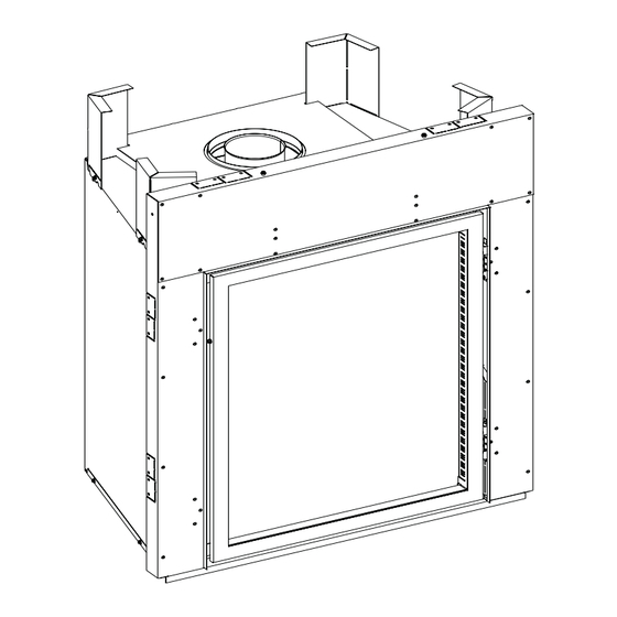
Page 7: Fireplace Dimensions
Fireplace DiMensions DiMensions (in inches) index Dimension Description DVtl27 letter The maximum height of firebox face (excluding standoffs) 47-3/8” The maximum width of the firebox face (excluding nailing flanges) 37-3/8” The maximum depth of the firebox 26” The height of the firebox opening 37” The width of the firebox opening 28-1/4” The interior depth of the firebox 20-1/2” The rear exterior width of the firebox 23-3/4” The height to the firebox standoffs Width from the left side of the box to the centerline of vent 18-11/16” Depth from back of box to centerline of top vent 8-11/16”... -
Page 8: Clearances
clearances clearance to coMBUstiBles Back 2-3/4" 2-3/4" Side 2-3/4” Floor 0" COMBUSTIBLES ALLOWED Top Framing Edge 0" 26” FROM SURFACE OF FACE TO 2-3/4” COMBUSTIBLES FRAMING HEADER DRYWALL 3/4" SURFACE OF FACE 6" 6" FROM FACE OPENING NON-COMBUSTIBLE FINISH MATERIAL TO COMBUSTIBLES, BOTH SIDES MUST COVER THE SURFACE OF THE FIREPLACE FACE... - Page 9 clearances (cont’D) clearances Clearance from top front edge of fireplace to ceiling is 40 inches. Clearance from side of fireplace to adjacent sidewall is 6 inches. 40” TO FIREPLACE OPENING 6” TO FIREPLACE OPENING ▼ Figure 4 coMBUstiBle Material No greeting cards, stockings or ornamentation of any type should be placed on or attached to the fireplace. The flow of heat out of the appliance can ignite combustibles. Figure 5 33740-17-0120 Page 9...
-
Page 10: Termination Clearances
terMination clearances Termination clearance for buildings with combustible and noncombustible exteriors. I = COMBUSTIBLE 12” = NONCOMBUSTIBLE 12” Figure 6 Vertical sidewall installations The graph showing the relationship between vertical and horizontal important! Minimum clearance between vent pipes and combustible side wall venting will help to determine the various vent lengths materials is 3 inch on top, and 1 inch (on bottom and sides). -
Page 11: Vent Terminal Clearances
Clearances are to heat resistant material (i.e. wood, metal). This the following shall be indicated: does not include vinyl. Empire Comfort Systems Inc. will not be held Clearance in accordance with local installation codes and the requirements of the responsible for heat damage caused from terminating under vinyl gas supplier. -
Page 12: Gas Supply
Gas sUpplY The gas pipeline can be brought in through the right side of the appliance only. Consult the current National Fuel Gas Code, ANSI Z223.1 installation code. recoMMenDeD Gas pipe DiaMeter schedule 40 pipe tubing, type l pipe inside Diameter outside Diameter length natural... -
Page 13: Locating Fireplace
Gas sUpplY (cont’D) installing a new Main Gas shut-off (check local code) The appliance and its individual shut off valve must be disconnected Each appliance should have its own manual gas shut-off. from supply piping system during any pressure testing of that system A manual main gas shut-off should be located in the vicinity of the at test pressures in excess of 1/2 psig (3.5 kPa). -
Page 14: Electrical Considerations
electrical consiDerations A factory installed junction box is located on the lower right side of caUtion the fireplace. Wiring must be fed to the junction box and attached with wire nuts to the control module power leads already fed into All wiring should be done by a qualified electrician and shall the junction box. -
Page 15: Installation
installation Framing and Finishing caUtion Measure fireplace dimensions and verify framing methods, and wall covering details before framing construction begins. Choose unit location. 2. Frame in fireplace with a header across the top. note: Fireplace framing can be built before or after the fireplace is set in place. Framing should be positioned to accommodate wall covering and fireplace facing material. The fireplace framing should be constructed of 2 x 4 lumber. The framing headers may rest on the fireplace standoffs. Refer to Figures 15 and 16 for minimum framing dimensions. - Page 16 installation (cont’D) Figure 18 Figure 20 Figure 19 Figure 21 Page 16 33740-17-0120...
- Page 17 installation (cont’D) Figure 23 Figure 22 HoriZontal Vent clearances Figure 24 Vent pipe clearance note: Maintain all clearances to combustibles as shown in Figures 1 and 2 on page 8. For horizontal vent, maintain a minimum 1 inch clearance to the bottom and sides of the vent, and 3 inches of clearance to combustibles above the vent pipe.
- Page 18 installation (cont’D) Vent runs Vertical, 90° elBoW WitH HoriZontal terMination In planning the installation for the fireplace, it is necessary to install (12 inches minimum vertical rise shown) certain components before the appliance is completely positioned and installed. These include the direct vent system, gas piping for the appliance and the electrical wiring. The appliance can be mounted on any of the following surfaces: 1. A flat, hard surface A raised wooden platform...
- Page 19 installation (cont’D) Vertical, 90° elBoW to HoriZontal oUt tHe Wall corner installation - Vertical, 90° elBoW to (12 inches minimum rise before elbow) HoriZontal oUt tHe Wall note: A “B” dimension greater than 18 inches will require a vertical rise before the elbow that is greater than 12 inches. See Venting graph on page 22.
-
Page 20: Vent System Identification
Vent sYsteM iDentiFication Begin the vent system installation by selecting the type of venting When selecting a vent system for use with the fireplace, refer to the to be installed and the path that it will take. Verify that clearances “Vent Fireplace” section in this manual to determine what systems are met throughout the path of the venting system. are acceptable. Check all clearances and venting components. Identify problems existing in the vent system, if any. Use pages 20 Determine how the vent system will be terminated out the side of to 27 for venting to eliminate issues after installation. -
Page 21: Venting Fireplace
VentinG Fireplace Below Grade installation When it is not possible to meet the required vent termination clearances of 12 inches above grade level, a snorkel kit is recommended. It allows installation depth down to 7 inches below grade level. The 7 inches is measured from the center of the horizontal vent pipe as it penetrates through the wall. - Page 22 VentinG Fireplace to Use the Vent Graph eXaMple c: Determine the height of the center of the horizontal vent pipe. If the horizontal run to the outer wall flange is 17 feet, the vertical Using this dimension on the Sidewall Vent Graph, locate the dimension from the floor of the unit to the center of the termination point it intersects with the slanted graph line. must not be less than 7 feet 6 inches.
-
Page 23: Top Vent - Horizontal Termination
top Vent - HoriZontal terMination one elbow two elbows note: Subtract 3 feet from the total horizontal measurement for each 90° elbow installed horizontally. Subtract 1-1/2 feet from the total horizontal measurement for each 45° elbow installed hori- zontally. eXaMple Vent rUns initial pipe a (Vertical) B (Horizontal) lenGtH 24”... -
Page 24: Top Vent - Vertical Termination
top Vent - Vertical terMination no elbows three elbows note: Subtract 3 feet from the total horizontal measurement for each 90° elbow installed horizontally. Subtract 1-1/2 feet from the total horizontal measurement for each 45° elbow installed hori- zontally. DiMensions MiniMUM MaXiMUM 10’ 40’ eXaMple Vent rUns Figure 37 initial pipe a (Vertical) B (Horizontal) -
Page 25: Vertical Termination
Vertical terMination Locate and mark the center point of the vent pipe using a nail on General Maintenance the underside of the roof. Drive the nail through the center point. Inspect venting system semi-annually as follows: Mark the outline of the roof hole around this center point. 1. - Page 26 Vertical terMination (cont’D) Vertical through the roof applications Your Gas Fireplace has been approved for: a) Vertical installations up to 40 feet in height. b) Two sets of 45° elbow offsets within these vertical installations. A vent pipe from 0 to a maximum of 8 feet can be used between elbows. c) Wall straps must be used to support offset pipe every 4 feet This application will require that you first determine the roof pitch and use the appropriate venting components.
- Page 27 Vertical terMination (cont’D) The included flue restrictor disc may be used in vertical vent runs of 10 to 40 feet as measured from the bottom of the fireplace. Use the restrictor disc when a more yellow flame is desired. If the flue restrictor is installed on a natural gas fireplace, the rear burner’s air shutter must be adjusted to 1/8-in. open. 33740-17-0120 Page 27...
-
Page 28: Framing And Finishing
FraMinG anD FinisHinG installing support Brackets Install a horizontal pipe support used for each 3 feet of horizontal run to framing members. Allow 3 inches of clearance to combustibles above 8 inch diameter pipe and elbows and 1 inches of clearance on both sides and bottom. - Page 29 FraMinG anD FinisHinG (cont’D) Vertical Firestops Vertical runs of this system which pass through ceilings require ONE ceiling firestop at the hole in each ceiling through which the vent passes. Position a plumb bob directly over the center of the vertical vent component and mark the ceiling to establish the center point of the vent.
-
Page 30: Fiber Panel Placement
FiBer panels note: install liner before positioning the logs in place. Figure 50 placinG tHe reQUireD FiBer panels anD Floor liner into Fireplace: Locate the Center Floor Liner, and place on the fireplace floor in front of the front burner. Locate the Left and Right Side Floor Liner and place on the bottom left and bottom right of fireplace floor. Shift the three Floor Liner sections as far forward as possible. Locate Rear Panel and place tight against rear wall into rear bottom bracket. Locate Left Panel and place into position against left-side firebox wall. Secure using front upper bracket and screw provided. -
Page 31: Glowing Embers
GloWinG eMBers 1. Apply a single layer of small “dime-sized” pieces of rock wool (glowing embers) in the shaded areas shown below. note: Pieces of glowing embers should be fluffed up prior to placement onto the burner. note: Replacement of loose material (glowing embers) must be purchased from Empire Comfort Systems, Inc. Application of excess loose material (glowing embers) may adversely affect performance of the appliance. WarninG all previously applied loose material must be removed prior to reapplication. -
Page 32: Log Placement
This should eliminate sooting on the log, and provide a more pleasing flame appearance. Replacement of glowing embers must be purchased from Empire Comfort Systems, Inc. Application of excess glowing embers may adversely affect performance of the appliance. WarninG all previously applied loose material must be re- moved prior to reapplication. - Page 33 loG placeMent attention: When ordering parts, it is very important that part number and description of part coincide. Front part number 31034 - right rear (a) part number 31034 - right rear (a) part number 31033 left rear (B) part number 31033 left rear (B) part number 31036 - left Front (c) part number 31036 - left Front (c) part number 31037 - right Front (D)
- Page 34 loG placeMent 1. Place Right Rear Log (A) onto the right-side pin on the rear burner. top VieW 2. Using right-hand, hold Right Rear Log (A) at approximately the angle shown. Front VieW Page 34 33740-17-0120...
- Page 35 loG placeMent 3. Place Left Rear Log (B) on left-side pin on rear burner and attach the top of the Left Rear Log(B) to the pin on Right Rear Log (A). top VieW Front VieW 33740-17-0120 Page 35...
- Page 36 loG placeMent 4. Place Right Front Log (D) on the two pins on the right-hand side of the front burner. top VieW Front VieW Page 36 33740-17-0120...
- Page 37 loG placeMent 5. Place Center Front Log (E) on tab in center of front burner. Orient as shown. top VieW Front VieW 33740-17-0120 Page 37...
- Page 38 loG placeMent 6. Place Left Front Log (C) onto the two pins on the left-hand side of the front burner. top VieW Front VieW Page 38 33740-17-0120...
- Page 39 loG placeMent 7. Place Right Corner Log (F) onto pin on Right Front Log (D). Rest opposite end of Right Corner Log (F) in the right corner of the firebox. top VieW Front VieW 33740-17-0120 Page 39...
- Page 40 loG placeMent 8. Place Center Rear Log (G) into recess onto the pin on the Left Front Log (C). top VieW Front VieW Page 40 33740-17-0120...
- Page 41 loG placeMent top VieW Front VieW 33740-17-0120 Page 41...
-
Page 42: Component Wiring Diagram
coMponent WirinG DiaGraM Figure 54 inDeX nUMBer Description part nUMBer WIRE HARNESS, LIGHT SOCKETS R11860 WIRE HARNESS, MODULE TO USER INTERFACE R11552 WIRE HARNESS, SPLIT-FLOW SOLENOID TO MODULE R11551 WIRE HARNESS, LIGHTS AND BLOWER TO MODULE R11741 WIRE HARNESS, JUNCTION BOX TO MODULE R11730 Page 42 33740-17-0120... -
Page 43: Multifunction Remote Operating Instructions
MUltiFUnction reMote operatinG instrUctions Figure 55 tecHnical Data remote control Supply voltage 4.5 V (three 1.5 V AAA batteries) Ambient temperature ratings 0-50°C (32 - 122°F) Radio frequency 315 MHz WarninG The transmitter and receiver are radio frequency devices. placing the receiver in or near metal may severely reduce the signal range. - Page 44 MUltiFUnction reMote operatinG instrUctions initializing the system for the First time With the batteries already installed in the Transmitter, push Remove the wall cover. Remove cover on the wall mounted the On button. The Receiver will “beep” four times to indicate battery back-up holder. see Figure 57. Install the four AA the Transmitter’s command is accepted and sets to the par- batteries into the wall mounted battery back-up holder then ticular code of that Transmitter.
- Page 45 MUltiFUnction reMote operatinG instrUctions turn on the appliance With the system OFF, press the ON/OFF Button on the Transmit- ter. The Transmitter display will show some other active Icons on the screen. At the same time the Receiver will activate the appli- ance. A single “beep” from the Receiver will confirm reception of the command. turn oFF the appliance With the system ON, press the ON/OFF Button on the Transmit- ter.
- Page 46 MUltiFUnction reMote operatinG instrUctions the thermostat Feature may be disabled if desired. smart thermostat (transmitter operation) With all three AAA type batteries installed: The Smart Thermostat function adjusts the flame height in ac- Take out one AAA battery. cordance to the difference between the set point temperature While re-inserting the AAA battery, Push and hold down the and the actual room temperatures.
- Page 47 MUltiFUnction reMote operatinG instrUctions Blower control (Fan) remote Dimmer control (light) If the appliance is equipped with a hot air circulating fan, the The auxiliary function controls the AUX power outlet by the dim- speed of the fan can be controlled by the Proflame system. mable light control. To activate this function, use the Mode Button (Figure 56) to index to the AUX icon.
- Page 48 MUltiFUnction reMote operatinG instrUctions split Flow control Remote Auxiliary Relay Control (optional with this fireplace) The secondary burner is controlled by the split Flow. To activate The auxiliary function controls the AUX relay outlet. To activate this function use the Mode Button (Figure 56) to index to the this function use the Mode Button (Figure 56) to index to the SPLIT FLOW mode icon.
- Page 49 MUltiFUnction reMote operatinG instrUctions continuous pilot/intermittent pilot (cpi/ipi) selection Button lock With the system in “OFF” position press the Mode Button (Figure This function will lock the Buttons to avoid unsupervised opera- 56) to index to the CPI mode icon. see Figures 79 and 80. tion. Pressing the Up Arrow Button will activate the CPI. Pressing the To activate this function, press the MODE and UP Buttons at the Down Arrow Button will return to IPI. A single “beep” will confirm same time.
- Page 50 MUltiFUnction reMote operatinG instrUctions Using the Fireplace without a remote control Lockout State Definition The fireplace can be turned ON (HI only) and OFF with the wall A lockout state is reached when an ignition error occurs. The switch. The fireplace flame ON/OFF is the only function that will lockout state will remain set in memory as long as the power sup- operate; no flame adjustment, light or blower will work when us- plies are applied.
-
Page 51: Control System Troubleshooting
control sYsteM troUBlesHootinG If the IFC is signaling lock out: The Verify the electrical connections’ integrity and board should be unlocked to make sure they are in accordance with the relevant reinitiate a pilot flame ignition (for Is the IFC board in system wiring diagram. - Page 52 control sYsteM troUBlesHootinG Replace IFC board. Main burner lights when the pilot only Replace the gas valve. should light. Verify the pilot flame fully engulfs the tip of the sense electrode. If not, replace the pilot assembly. Replace the pilot assembly. Carefully clean the electrical connections of the sense cable and the IFC board sense cable connection.
-
Page 53: Lighting Instructions
liGHtinG instrUctions For YoUr saFetY reaD BeFore liGHtinG WarninG If you do not follow these instructions exactly, a fire or explosion may result causing property damage, personal injury, or loss of life. a. this appliance must be lighted with the remote control. c. -
Page 54: Fireplace Parts View
Fireplace parts VieW 19 20 Page 54 33740-17-0120... -
Page 55: Fireplace Parts List
Fireplace parts list inDeX part inDeX part Description Description 33821 FLOOR LINER, LEFT ORIFICE 1.45mm, PROPANE P208 (REAR) 33823 FLOOR LINER, CENTER R11675 ORIFICE HOLDER 33822 FLOOR LINER, RIGHT R7572 JAMB NUT BRICK PANEL, 33786 LEFT 33633 THERMOCOUPLE SHIELD BRICK PANEL, R11585 PILOT, NATURAL 33787... -
Page 56: Maintenance And Service
Maintenance anD serVice Maintenance WarninG Maintenance frequency must be determined individually for each application. Some considerations are: This appliance is equipped for natural gas or propane gas. • Exposure to water, dirt, chemicals and heat can damage the Field conversion is not permitted. gas control and shut down the control system. •... - Page 57 Maintenance anD serVice (cont’D) note WarninG It is normal for appliances fabricated of steel to give off some the use of substitute glass will void all product warranties. expansion and/or contraction noise during the start up or cool care must be taken to avoid breakage of the glass. down cycle. Similar noises are found with your furnace heat Under no circumstances should this appliance be operated exchanger or car engine.
- Page 58 Maintenance anD serVice (cont’D) Figure 83 Figure 85 Wiring If any of the original wire supplied with this unit must be replaced, it must be replace with 18 GA. 150°C wire or its equivalent. Figure 84 Page 58 33740-17-0120...
- Page 59 Maintenance anD serVice (cont’D) accessing Gas Valve and controls Remove the Offset Frame and Glass Frame. Remove the Burner Components Heat Shield. see Figure 86. 3. Remove logs from firebox. Remove the liner bracket on top of the right-hand liner panel and remove right hand liner panel. Remove the Access Plate.
-
Page 60: Important Safety Information
iMportant saFetY inForMation Before enclosing the vent pipe assembly, operate caUtion the appliance to ensure it is venting properly. if the glass is cracked or damaged in any way, it should be replaced only with a complete glass frame assembly WarninG from empire. -
Page 61: Safety Information For Users Of Propane Gas
saFetY inForMation For Users oF propane Gas Propane is a flammable gas which can cause fires and The odorant in escaped gas can adsorb or absorb onto or explosions. in its natural state, propane is odorless and into walls, masonry and other materials and fabrics in a room. colorless. -
Page 62: Requirements For Massachusetts
reQUireMents For MassacHUsetts For all side wall horizontally vented gas fueled equipment 3. SIGNAGE. A metal or plastic identification plate shall be installed in every dwelling, building or structure used in permanently mounted to the exterior of the building at a whole or in part for residential purposes, including those minimum height of eight feet above grade directly in line owned or operated by the Commonwealth and where the with the exhaust vent termination for the horizontally... -
Page 63: Master Parts Distributor List
This list changes from time to time. For the current list, please click on the Master Parts button at www.empirecomfort.com. Please note: Master Parts Distributors are independent businesses that stock the most commonly ordered Original Equipment repair parts for Heaters, Grills, and Fireplaces manufactured by Empire Comfort Systems Inc. Dey Distributing F. -
Page 64: Warranty
Shipping expenses are not covered. If, after contacting your Empire dealer, service received has not been satisfactory, contact: Consumer Relations Department, Empire Comfort Systems Inc., PO Box 529, Belleville, Illinois 62222, or send an e-mail to info@empirecomfort.com with “Consumer Relations” in the subject line.
Need help?
Do you have a question about the White Mountain Hearth DVTL27FP90N-1 and is the answer not in the manual?
Questions and answers