Table of Contents
Advertisement
Quick Links
Advertisement
Table of Contents
Troubleshooting

Related Manuals for Empire Comfort Systems Studio Series


Summary of Contents for Empire Comfort Systems Studio Series
- Page 1 This Owner's Manual is provided and hosted by Appliance Factory Parts. EMPIRE DVX42DP91-2 Owner's Manual Shop genuine replacement parts for EMPIRE DVX42DP91-2 Find Your EMPIRE Fireplace Parts - Select From 642 Models -------- Manual continues below --------...
- Page 2 INSTALLATION INSTRUCTIONS EMPIRE EMPIRE OWNER’S MANUAL Comfort Systems The Studio Series Direct Vent Zero LUXURY DIRECT VENT Clearance Gas Fireplace Heater GAS FIREPLACE HEATER MODEL SERIES MILLIVOLT STANDING PILOT DVX36DP31(N,P)-2 DVX42DP31(N,P)-2 DIRECT IGNITION DVX36DP51N-1 DVX42DP51N-1 INTERMITTENT PILOT DVX36DP71(N,P)-2 DVX42DP71(N,P)-2 WARNING...
-
Page 3: Table Of Contents
TABLE OF CONTENTS Section Page Important Safety Information ................................3 Safety Information for Users of LP Gas ..............................4 Requirements for Massachusetts ................................5 Introduction ......................................6 Specification ......................................7 Fireplace Dimensions ....................................7 Clearances......................................8 Locating Fireplace ....................................8 Gas Supply......................................9 Installation ..................................... 10-13 Venting Fireplace - Top ................................. 14-17 Examples - Top Vent Run ..................................18 DVVK-4FV Direct Vent Termination Kit ............................. -
Page 4: Important Safety Information
IMPORTANT SAFETY INFORMATION Before enclosing the vent pipe assembly, operate the appliance to ensure it is venting properly. DO NOT OPERATE THIS APPLIANCE WITHOUT GLASS FRONT PANEL INSTALLED • If this appliance is installed directly on carpeting, tile • Adequate accessibility clearances for servicing and proper or other combustible material other than wood flooring operation. -
Page 5: Safety Information For Users Of Lp Gas
SAFETY INFORMATION FOR USERS OF LP GAS Propane (LP-Gas) is a flammable gas which can cause fires by point with the members of your household. Someday when and explosions. In its natural state, propane is odorless and there may not be a minute to lose, everyone’s safety will depend colorless. -
Page 6: Requirements For Massachusetts
REQUIREMENTS FOR MASSACHUSETTS For all side wall horizontally vented gas fueled equipment installed 3. SIGNAGE. A metal or plastic identification plate shall be in every dwelling, building or structure used in whole or in part permanently mounted to the exterior of the building at a for residential purposes, including those owned or operated by the minimum height of eight (8) feet above grade directly in line Commonwealth and where the side wall exhaust vent termination... -
Page 7: Introduction
(a) the installation or replacement of gas piping or (b) the • Modification of the fireplace or direct vent system. connection, installation, repair or servicing of equipment, who is • Installation other than as instructed by Empire Comfort Systems, experienced in such work, familiar with all precautions required Inc. -
Page 8: Specification
SPECIFICATIONS DVX36 NAT DVX36 LP DVX42 NAT DVX42 LP Input Btu/hr Maximum 35,000 30,000 37,500 35,000 Btu/hr Minimum 24,000 21,000 26,000 24,000 KWH (Maximum) 10.3 11.0 10.3 (Minimum) #31 (P-209) - DVP42DP(3,7,9) #50 (P-245) - DVP42DP(3,7,9) Orifice #32 (P-211) 1.65 mm (P-250) 2.75 mm (P-305) - DVP42DP5 1.80 mm (P-304) - DVP42DP5 Air Shutter Opening... -
Page 9: Clearances
CLEARANCES Mantel Chart (Figure 3) Clearance to Combustibles Back 0" (0 mm) 12” (305mm) Side 0" (0 mm) 10” (254mm) Floor 0" (0 mm) MANTEL Top Stand-off 0" (0 mm) Top Framing Edge 6" (152 mm) COMBUSTIBLE TRIM AND 8” MANTELS ALLOWED IN SHADED AREA 6”... -
Page 10: Gas Supply
GAS SUPPLY Installing a New Main Gas Cock The gas pipeline can be brought in through the right or left side of the appliance. Consult the current National Fuel Gas Code, ANSI Each appliance should have its own manual gas cock. Z223.1 CAN/CGA-B149 (.1 or .2) installation code. -
Page 11: Installation
INSTALLATION Framing and Finishing VENT PIPE Choose unit location. Frame in fireplace with a header across the top. It is important to allow for finished face when setting the depth of the frame. Attach fireplace to frame using adjustable nailing flange. Preset depth to suit facing material (adjustable to 3/8", 1/2"... - Page 12 INSTALLATION (continued) DVX36 DVX42 "A" 40 7/8" 40 7/8" NAIL OR OTHER "B" 40 3/8" 43 3/8" SUITABLE FASTENER Figure 10 "C" 19 7/8" 19 7/8" Framing (Figure 11) Figure 11 Fireplace framing can be built before or after the fireplace is set in place.
- Page 13 Flush Wall Installation Attention: Cold climate installation recommendation: When installing this unit against a non-insulated exterior wall, it is recommended that the outer walls be insulated to conform to applicable insulation codes. Vent Runs (Figures 14, 15, and 16) In planning the installation for the fireplace, it is necessary to install certain components before the appliance is completely positioned and installed.
- Page 14 INSTALLATION (continued) VERTICAL, 90° ELBOW TO CORNER INSTALLATION VERTICAL, 90° ELBOW TO HORIZONTAL OUT THE WALL HORIZONTAL OUT THE WALL “A” WALL FIRESTOP/ 90º ELBOW “A” THIMBLE PIPE LENGTH “B” 6” (152mm) MINIMUM “C” VENT 9” (229mm) “D” MINIMUM VENT CAP WALL FIRESTOP/ THIMBLE “C”...
-
Page 15: Venting Fireplace - Top
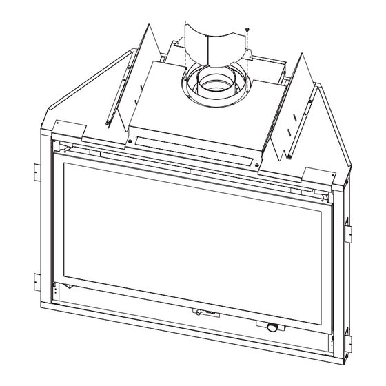
VENTING FIREPLACE - TOP Venting Graph (Dimensions in Feet) To Use the Vent Graph (Figure 17) 1. Determine the height of the center of the horizontal vent pipe. Using this dimension on the Sidewall Vent Graph, TOP EXIT - VERTICAL AND HORIZONTAL TERMINATION (DIMENSIONS IN FEET) locate the point it intersects with the slanted graph line. - Page 16 VENTING FIREPLACE - TOP (continued) Installation of Flue Heat Shield HOLES FOR 42” MODELS Remove flue insulation. Remove (2) screws on outside of inlet vent adapter. See Figure 18. Lift top shield placing flue heat shield around flue. Replace (2) screws on outside of inlet vent adapter. See Figure 19.
- Page 17 VENTING FIREPLACE - TOP (continued) Below Grade Installation When it is not possible to meet the required vent terminal clearances of 12" (305mm) above grade level, a snorkel kit is recommended. It allows installation depth down to 7" (178 mm) below grade level. The 7"...
- Page 18 10” (254mm) 12” (305mm) SEE CHART FOR PERMISSIBLE “H” AND “V” DIMENSIONS CENTER OF ELBOW STRAIGHT OUT (MINIMUM) Figure 24 Figure 23 MINIMUM HOLE LOCATION DIMENSIONS FOR THROUGH THE WALL HORIZONTAL INSTALLATIONS WITH 90 DEGREE ELBOW OFF TOP OF FIREPLACE FIREPLACE HARD ELBOW DIMENSIONS SERIES...
-
Page 19: Examples - Top Vent Run
EXAMPLES - TOP VENT RUN Example H2 3ft, H3 1ft = 4ft (90° + 90° + 90°) = 6ft V1 = 21ft H = 10ft V = 21ft Figure 27 Figure 26 Example H1 = 2ft V1 = 20ft H = 2ft V = 20ft Figure 28 Page 18... -
Page 20: Dvvk-4Fv Direct Vent Termination Kit
DVVK-4FV DIRECT VENT TERMINATION KIT Installation Instructions This termination kit can only be used with Empire Comfort Systems direct vent fireplaces listed for use with DVVK-4FV Vertical Flex Vent Kit. Please review the instructions packaged with your fireplace and verify the fireplace model number. - Page 21 DVVK-4FV DIRECT VENT TERMINATION KIT (cont.) PRE-INSTALLATION INFORMATION: Items Required For Installation: Tools Building Supplies Phillips Screwdriver Framing Materials Hammer Wall Finishing Materials Saw and/or saber saw Caulking Material (Noncombustible) Level Support Strap supplies Measuring Tape Electric Drill and Bits Pliers Square Tin Snips...
- Page 22 DVVK-4FV DIRECT VENT TERMINATION KIT (cont.) Step-By-Step Installation For Flex DV Kit Unpack vent components and check all items for shipping 5. Next, determine the location for the cutout in the roof open- damage. ing. This opening must be large enough to provide a mini- For this venting system to operate as designed it is depen- mum 1”...
- Page 23 DVVK-4FV DIRECT VENT TERMINATION KIT (cont.) 10. With the flex vent assembly and the 48” long hard pipe com- 13. Now the pre-assembled vent system may be carried to the ponents laid out on the floor, begin securing these parts to- roof, then lowered through the roof cutout opening (see step gether.
- Page 24 DVVK-4FV DIRECT VENT TERMINATION KIT (cont.) 17. To attach the vent connections at the fireplace, be sure the 7” 21. An additional storm collar band is provided in kit that may be diameter adapter collar has been installed per step 3. Apply used as an attic insulation shield.
- Page 25 DVVK-4FV DIRECT VENT TERMINATION KIT (cont.) VERTICAL TERMINATION STORM COLLAR 4’ LONG RIGID PIPE ROOF FLASHING ADJUSTABLE ROOF JACK ASSEMBLY ROOF EXTERIOR CLEARANCE TO COMBUSTIBLES REQUIRED FROM VENT PIPE CLAMPS AT FLUE & INLET VENT CONNECTIONS ADJUSTABLE STORM COLLAR (USE TO FIRESTOP/THIMBLE KEEP INSULATION OUT OF ASSEMBLY...
- Page 26 DVVK-4FV DIRECT VENT TERMINATION KIT (cont.) Vertical Flex Termination Kit Item Quantity Number Item Description Repair Part No. Supplied 4”/7” Vertical Termination Cap MF100038 Roof Support Kit MF100503 2 Ply Alum Flex 4” Diameter by 6 ft. MF04ALA2F006 2 Ply Alum Flex 7” Diameter by 6 ft. MF07ALA2F006 4”/7”...
-
Page 27: Dvvk-4Re Vent Kit Installation Instructions
DVVK-4RE VENT KIT INSTALLATION INSTRUCTIONS CAUTION: Sharp edges, use protective gloves when installing. Tools Needed for Installation: Sheet metal snips 5/16” nut driver Phillips head screwdriver - #2 High temperature sealant or furnace cement rated for continuous use at 1,000 F minimum Measuring tape Parts Verification... - Page 28 DVVK-4RE VENT KIT INSTALLATION INSTRUCTIONS (continued) 7. Remove outside mounting plate with tube attached from wall. Mark and cut the extra length of the 6 5/8” (168 mm) diameter VINYL SIDING KIT DV822 tube from the opposite end. Do not crimp or enlarge tube. OUTSIDE MOUNTING 8.
- Page 29 DVVK-4RE VENT KIT INSTALLATION INSTRUCTIONS (continued) Follow correct option according to venting method. Connecting to Rigid Vent System If the air inlet and flue outlet tubes are to be connected to a rigid Connecting Directly to Fireplace venting system (and not directly to the back of the unit), then do If the air inlet and flue outlet tubes are to be connected directly to not use the gasket provided.
-
Page 30: Dvvk-4F Flex Vent Instructions
DVVK-4F FLEX VENT INSTRUCTIONS The DVVK-4F FLEX VENT KIT includes the following components: • (1) Horizontal Termination Cap • (1) 7" diameter Outer Vent adapter collar • (1) 4-foot section of Flex vent with spacers (4" flue/7" outer • (1) Wall Firestop/Thimble Assembly pipe) •... -
Page 31: Termination Clearances
TERMINATION CLEARANCES Termination clearance for buildings with combustible and noncombustible exteriors. INSIDE CORNER OUTSIDE CORNER RECESSED LOCATION “A” = COMBUSTIBLE 9” (229mm) “F” = COMBUSTIBLE 6” (152mm) = NONCOMBUSTIBLE 2” (51mm) = NONCOMBUSTIBLE 6” (152mm) BALCONY BALCONY WITH PERPENDICULAR SIDE WALL WITH NO SIDE WALL “C”... -
Page 32: Vent Clearances
VENT CLEARANCES AREA WHERE TERMINAL IS NOT PERMITTED VENT TERMINAL AIR SUPPLY INLET Figure 47 *Clearance above grade, veranda, porch, deck or balcony clearance to non-mechanical air supply inlet to building or [*12 inches (30cm) minimum] the combustion air inlet to any other appliance [*12 inches (30cm) minimum for appliances ≤... -
Page 33: Vent System Identification
VENT SYSTEM IDENTIFICATION Special Venting Components (Simpson Duravent) See Empire Comfort Systems Retail Price List for Simpson Duravent part numbers and pricing. Special DV Vent Kits Special DV Vent Kits Available from Empire Comfort Systems, Inc. dealers. Available from Empire Comfort Systems, Inc. dealers. -
Page 34: Framing And Finishing
FRAMING AND FINISHING Installing Support Brackets (Figure 49) A horizontal pipe support MUST BE used for each 3 feet of horizontal run. The pipe supports should be placed around the pipe and nailed in place to framing members. There MUST BE a 3 inch clearance to combustibles above flue pipe and elbows and 1 inch clearance on both sides and bottom of the flue pipe to combustibles on all horizontal pipe sections and elbows. - Page 35 FRAMING AND FINISHING (continued) EXISTING CEILING JOISTS NAILS, 4 REQUIRED CEILING FIRESTOP NEW FRAMING CEILING BELOW Vent Size Vent Size 6 5/8" 10" 10" 6 5/8" 10" 10" 8" 10 1/2" 10 1/2" 8" 10 1/2" 10 1/2" Figure 51 Figure 53 See Horizontal Termination Page 35 and Vertical Termination Pages 37 and 38.
-
Page 36: Horizontal Termination
HORIZONTAL TERMINATION NOTE: Termination cap should pass through the wall firestop from the exterior of the building. Adjust the termination cap to its final exterior position on the building. Warning: Termination cap must be positioned so that arrow is pointing up. CUT VINYL SIDING AWAY Attach the termination cap with the four wood screws provided. -
Page 37: Dvvk-5F Flex Vent Instructions
DVVK-5F FLEX VENT INSTRUCTIONS The DVVK-5F FLEX VENT KIT includes the following components: • (1) Horizontal Termination Cap • (1) Wall Firestop/Thimble Assembly • (1) 4-foot section of Flex vent with spacers (5" flue/8" • Hardware pack that includes band clamps and screws outer pipe) with flue adapter collar Flex venting can only be installed vertically off of the DVX Series fireplaces. -
Page 38: Vertical Termination
VERTICAL TERMINATION Locate and mark the center point of the venting pipe. Using a nail on the underside of the roof and drive this nail through this center point. Make the outline of the roof hole around this center point. NOTE: Size of the roof hole dimensions depend on the pitch of the roof. - Page 39 All damaged gaskets on the glass frame assembly and combustion chamber must be replaced by a qualified service person. If damage occurs to the combustion chamber, it must be replaced by a qualified service person. Contact Empire Comfort Systems, Inc. for replacement parts. Page 38...
-
Page 40: Log Identification
LOG IDENTIFICATION REAR BOTTOM LOG (A) REAR TOP LOG (B) Part Number - R9228 Part Number - R9222 BOTTOM LEFT LOG (C) BOTTOM LEFT CENTER LOG (D) Part Number - R9227 Part Number - R9372 BOTTOM RIGHT CENTER LOG (E) BOTTOM RIGHT LOG (F) Part Number - R9225 Part Number - R9229... -
Page 41: Log Placement (13 Log Set)
LOG PLACEMENT (13 LOG SET) 6. Place Bottom Left Log (C) on far left pin of burner. The "lip" Before you begin: If you are installing logs into the DVX36 or of the log will hang off the side of the burner. DVX42 model then this fireplace is supplied with a set of 13 ceramic fiber logs. - Page 42 LOG PLACEMENT (13 LOG SET) Place Bottom Right Log (F) on far right pin on the burner. The 12. Place Top Left Log (I) on two left pins on (B) Log. "lip" of the log will hang off the side of the burner. 13.
- Page 43 LOG PLACEMENT (13 LOG SET) 15. Place Front Center Log (L) between third and fourth grates on 18. Replace glass door onto firebox. the burner. The short "Y" branch will point left and the bottom 19. Secure the two glass frame spring clamps at bottom of of the "Y"...
- Page 44 LOG PLACEMENT (13 LOG SET) Figure 65 Figure 66 Log Set Parts List Index Letter Part Number Description R9228 Rear Bottom Log R9222 Rear Top Log R9227 Bottom Left Log R9372 Bottom Left Center Log R9225 Bottom Right Center Log R9229 Bottom Right Log R9223...
-
Page 45: Operating Instructions
OPERATING INSTRUCTIONS 750 Millivolt System The OWNER should carefully read and follow these operating The standing pilot (750 millivolt system) is a continuous burning instructions at all times. Lower the door assembly to view the gas pilot. The pilot remains ON even when the main burner is OFF. controls for the fireplace. - Page 46 OPERATING INSTRUCTIONS (continued) STANDING PILOT OPERATING INSTRUCTIONS Installation of Remote Receiver Remote/Off/On Switch Place remote receiver on the floor of fireplace behind the louver The fireplace is equipped with a Remote/OFF/ON switch. A wire as far forward as possible. harness is attached to the Remote/OFF/ON switch. The red, black Attention: The velcro loop and hook are not necessary in this and green (wires) female push-ons attach to the Remote/OFF/ installation but can be used to secure remote receiver.
-
Page 47: Standing Pilot Wiring Diagram
STANDING PILOT WIRING DIAGRAM REMOTE CONTROL RECEIVER (OPTIONAL) THERMOSTAT (OPTIONAL) WALL SWITCH GAS VALVE REMOTE/OFF/ON SWITCH (OPTIONAL) REMOTE CONTROL RECEIVER REMOTE/OFF/ON SWITCH GREEN REMOTE BLACK GREEN THERMOPILE IF ANY OF THE ORIGINAL WIRE AS SUPPLIED WITH THIS UNIT MUST BE REPLACED, IT MUST BE REPLACED WITH NO. -
Page 48: Standing Pilot Lighting Instructions
STANDING PILOT LIGHTING INSTRUCTIONS FOR YOUR SAFETY, READ BEFORE LIGHTING WARNING: If you do not follow these instructions exactly, a fire or explosion may result causing property damage, personal injury or loss of life. A. This appliance has a pilot which must be lighted by hand. •... -
Page 49: Standing Pilot Troubleshooting
STANDING PILOT TROUBLESHOOTING With proper installation and maintenance, your new Direct Vent Gas Fireplace will provide years of trouble-free service. If you do experience a problem, refer to the Trouble Shooting Guide below. This guide will assist a qualified service person in the diagnosis of problems and the corrective action to be taken. -
Page 50: Direct Ignition Wiring Diagram
DIRECT IGNITION WIRING DIAGRAM GAS VALVE SPARK IGNITOR VALVE DE GAZ (OPTIONAL) WALL SWITCH OR THERMOSTAT ÉTINCELLE ALLUMER INTERRUPTEUR MURAL (FACULTATIVE) CONTROL MODULE (OPTIONAL) REMOTE CONTROL AUTORITÉ MODULE RECEIVER 120V (FACULATIVE) CONTROLE E DISTANCE DU RECEPTEUR 120 VAC LINE BLACK NOIR 120 VAC RTN BLACK NOIR WHITE BLANC... -
Page 51: Direct Ignition Lighting Instructions
DIRECT IGNITION LIGHTING INSTRUCTIONS FOR YOUR SAFETY READ BEFORE LIGHTING WARNING: IF YOU DO NOT FOLLOW THESE INSTRUCTIONS EXACTLY, A FIRE OR EXPLOSION MAY RESULT CAUSING PROPERTY DAMAGE, PERSONAL INJURY, OR LOSS OF LIFE. A. BEFORE LIGHTING smell all around the appliance area B. -
Page 52: Initial Start Up Gas Line Purge
INITIAL START UP GAS LINE PURGE NOTE: UNIT MUST BE PROPERLY GROUNDED FOR ELECTRONIC IGNITION TO FUNCTION. On initial installation, or after extended periods where the fireplace has not been used, gas lines may require purging. The installer or qualified service person may use the following purge procedures to prevent the delays that would be caused by waiting for the lockout periods between tries for ignition. -
Page 53: Direct Ignition Propane/Lp Gas Conversion
DIRECT IGNITION PROPANE/LP GAS CONVERSION The conversion shall be carried out in accordance with the 12. Install propane/LP main burner orifice marked 1.65 MM for requirements of the provincial authorities having jurisdiction DVX36 or marked 1.80 MM for DVX42. and in accordance with the requirements of the CSA B149.2 Important: Failure to install the correct orifice will result in installation code (Canada) and with the requirements of the unit over-firing that could overheat the appliance and result... - Page 54 DIRECT IGNITION PROPANE/LP GAS CONVERSION Maxitrol Valve Conversion REGULATOR FITTING NOTE: STAMPED WITH GAS TYPE SET FOR USE Figure 72 Model AIR SHUTTER BURNER ORIFICE SETTINGS Opening "A" Propane/LP Orifice DVX36 FULL OPEN 1.65 MM DVX42 FULL OPEN 1.80 MM Figure 71 26929-0-0110 Page 53...
-
Page 55: Intermittent Pilot Operating Instructions
INTERMITTENT PILOT OPERATING INSTRUCTIONS Provided on the intermittent pilot wiring harness are two (2) stripped The intermittent pilot (120/24 volt system) is ON when the main burner is ON. When the main burner is OFF the intermittent pilot and bare wires that are labeled THERMOSTAT. The wires will be used for attachment of 24 volt thermostat, optional FWS-1 wall is OFF. -
Page 56: Intermittent Pilot Lighting Instructions
INTERMITTENT PILOT LIGHTING INSTRUCTIONS FOR YOUR SAFETY READ BEFORE LIGHTING WARNING: If you do not follow these instructions exactly, a fire or explosion may result causing property damage, personal injury or loss of life. A. This appliance is equipped with an ignition device •... -
Page 57: Intermittent Pilot Troubleshooting
A. Turn the thermostat to its lowest setting. B. Wait one minute. The Service Department at Empire Comfort Systems, Inc. may be As you do Steps 4 and 5, watch for points where operation contacted to assist in servicing furnace. - Page 58 INTERMITTENT PILOT TROUBLESHOOTING (continued) spark generator and energizes the second main valve operator. The Safety Lockout second main valve opens and gas flows to the main burner, where S8600H provides 100 percent shutoff, or safety lockout. A timer it is ignited by the pilot burner. The flame current also holds the starts timing the moment the trial for ignition starts.
- Page 59 INTERMITTENT PILOT TROUBLESHOOTING (continued) Important WARNING 1. The following service procedures are provided as a general When performing the following steps, do not touch stripped guide. end of jumper or SPARK terminal. The ignition circuit 2. Meter readings between gas control and ignition module must generates 13,000 volts at 25 pf load and electrical shock be taken within the trial for ignition period.
- Page 60 INTERMITTENT PILOT TROUBLESHOOTING (continued) 26929-0-0110 Page 59...
- Page 61 INTERMITTENT PILOT TROUBLESHOOTING (continued) Green LED Status Codes Green LED Flash Code (X + Y) Indicates Next System Action Recommended Service Action No “Call for Heat” Not applicable None Flash Fast Startup-Flame sense calibration Not applicable None Heart Beat Normal operation Not applicable None Recycle...
-
Page 62: Rf Operating Instructions
RF OPERATING INSTRUCTIONS RF VALVE OPERATION (AF-4040 Electronic Gas Valve sys- 2. When the remote/off switch is in the OFF position the appli- tem only) ance will operate from an appliance mounted rocker switch Please refer to the separate instructions for detailed operation and (#3) or optional wall switch connected to the two (2) BROWN programming of the Multi-function Remote Control. -
Page 63: Rf Maintenance
RF MAINTENANCE INSTRUCTIONS MAINTENANCE TROUBLESHOOTING Maintenance frequency must be determined individually for each IMPORTANT: All service and trouble-shooting procedures should be performed by an experienced qualified service technician. application. Some considerations are: • Exposure to water, dirt, chemicals and heat can damage the If the pilot will not stay lit: gas control and shut down the control system. -
Page 64: Rf Wiring Diagram
RF WIRING DIAGRAM BLOWER BATTERY BACK-UP 120V EXTENSION LIGHT TRANSFORMER MODULE (OPTIONAL) ON/OFF BROWN SWITCH WHITE GREEN GAS CONTROL ORANGE VALVE Stepper PILOT Motor MAIN (GND) PILOT ELECTRONIC WHITE CONTROL MODULE ORANGE JUNCTION BOX Note: For "RF" Fireplace models with Premium Multi-Function Remote Control, Refer to the separate instructions for operation of the remote control system. -
Page 65: Rf Lighting Instructions
RF STANDING PILOT LIGHTING INSTRUCTIONS FOR YOUR SAFETY READ BEFORE LIGHTING WARNING: IF YOU DO NOT FOLLOW THESE INSTRUCTIONS EXACTLY, A FIRE OR EXPLOSION MAY RESULT CAUSING PROPERTY DAMAGE, PERSONAL INJURY, OR LOSS OF LIFE. A. This appliance has a pilot which must be lighted by C. -
Page 66: Maintenance And Service
MAINTENANCE AND SERVICE Glass Cleaning Please Note It will be necessary to clean the glass periodically. During start-up It is normal for appliances fabricated of steel to give off condensation, which is normal, forms on the inside of the glass and some expansion and/or contraction noise during the start causes lint, dust and other airborne particles to cling to the glass up or cool down cycle. - Page 67 MAINTENANCE AND SERVICE Glass Removal and Replacement (Figures 77 and 78) Remove decorative front doors (where applicable) by opening and lifting straight up. Remove decorative front by tilting lower portion forward to release ball catch and lifting front off mounting bracket. See Figure 74.
-
Page 68: Parts View
PARTS VIEW DI VALVE ASSEMBLY BLOWER ASSEMBLY MILLIVOLT VALVE ASSEMBLY RF VALVE ASSEMBLY IP VALVE ASSEMBLY Note: Refer to page 43 when ordering logs. 26929-0-0110 Page 67... -
Page 69: Dvx36Dp(31,51,71,91) Parts List
DVX36DP(31,51,71,91) PARTS LIST Part Number Index No. Description DVX36DP31 DVX36DP51 DVX36DP71 DVX36DP91 R9347 R9347 R9347 R9347 Insulation, Top Shield 23437 23437 23437 23437 Top Shield 23219 23219 23219 23219 Top Standoff (Qty. 2) R7566 R7566 R7566 R7566 Vent Adapter R7574 R7574 R7574 R7574... - Page 70 DVX36DP(31,51,71,91) PARTS LIST Part Number Index No. Description DVX36DP31 DVX36DP51 DVX36DP71 DVX36DP91 R2423 R2423 R2423 R2423 5/16" Male Connector R7578 R7733 R5746 R10415 Gas Valve (LPG) R7577 R7733 R5745 R10415 Gas Valve (Nat) 17161 20207 25640 26307 Gas Valve Bracket 23502 23502 23502...
-
Page 71: Dvx42Dp(31,51,71,91) Parts List
DVX42DP(31,51,71,91) PARTS LIST Part Number Index No. Description DVX42DP31 DVX42DP51 DVX42DP71 DVX42DP91 R9348 R9348 R9348 R9348 Insulation, Top Shield 23437 23437 23437 23437 Top Shield 23219 23219 23219 23219 Top Standoff (Qty. 2) R7567 R7567 R7567 R7567 Vent Adapter R7573 R7573 R7573 R7573... - Page 72 DVX42DP(31,51,71,91) PARTS LIST Part Number Index No. Description DVX42DP31 DVX42DP51 DVX42DP71 DVX42DP91 R2423 R2423 R2423 R2423 5/16" Male Connector R7578 R7733 R5746 R10415 Gas Valve (LPG) R7577 R7733 R5745 R10415 Gas Valve (Nat) 17161 20207 25640 26307 Gas Valve Bracket 23502 23502 23502...
-
Page 73: Fbb4 Variable Speed Blower Installation
FBB4 VARIABLE SPEED BLOWER INSTALLATION Attention: Install blower assembly before connecting gas inlet 5. Insert blower assembly into interior, bottom of fireplace. supply line Position blower assembly behind gas valve, align notch on back of blower assembly with center screw on fireplace back Note: Junction box on right side of fireplace must be pre-wired at and push blower assembly against fireplace back. -
Page 74: Junction Box Wiring Installation Instructions
FBB4 VARIABLE SPEED BLOWER INSTALLATION FBB4 B L O W E R A S S E M B LY COMPLETE R7649 FAN CONTROL R4192 SPEED CONTROL KNOB R4186 SPEED CONTROL 110 VOLT AC JUNCTION BOX BLACK SWITCH WHITE GROUND SPEED CONTROL JUNCTION BOX WIRING INSTALLATION INSTRUCTIONS CAUTION: ALL WIRING SHOULD BE DONE BY A QUALIFIED ELECTRICIAN AND SHALL BE IN COMPLIANCE... -
Page 75: Accent Lamp
ACCENT LAMP Your Luxury Direct Vent Gas Fireplace comes equipped with our COVER "Accent Lamp." The light has been pre-wired and is controlled from the Rheostat. If in the event the lamp or lens needs to be replaced, follow the instructions below: Unplug the Accent Lamp/transformer from the junction box inside the fireplace. -
Page 76: Accessories
ACCESSORIES The following accessory parts must be obtained from your Empire Comfort Systems dealer. If you need additional information contact your dealer. Simulated Stone Panels The simulated stone panels were designed to enhance the appearance of your fireplace, imitating the look of authentic DVP36XG masonry. -
Page 77: Master Parts Distributor List
For the current list, please click on the Master Parts button at www.empirecomfort.com. Please note: Master Parts Distributors are independent businesses that stock the most commonly ordered Original Equipment repair parts for Heaters, Grills, and Fireplaces manufactured by Empire Comfort Systems Inc. Star-Fire Distributors... -
Page 78: Quick Reference Guide
EMPIRE EMPIRE 918 Freeburg Avenue Belleville, Illinois 62220-2623 Comfort Systems The Studio Series Direct Vent Gas Fireplace Heater MILLIVOLT STANDING PILOT: DVX36DP31(N,P)-2; DVX42DP31(N,P)-2 DIRECT IGNITION: DVX36DP51N-1; DVX42DP51N-1 INTERMITTENT PILOT: DVX36DP71(N,P)-2; DVX42DP71(N,P)-2 REMOTE RF MODELS: DVX36DP91(N,P)-2; DVX42DP91(N,P)-2 Fireplace requires one of the following fronts:... - Page 79 EMPIRE EMPIRE 918 Freeburg Avenue Belleville, Illinois 62220-2623 Comfort Systems The Studio Series Direct Vent Gas Fireplace Heater MILLIVOLT STANDING PILOT: DVX36DP31(N,P)-2; DVX42DP31(N,P)-2 DIRECT IGNITION: DVX36DP51N-1; DVX42DP51N-1 INTERMITTENT PILOT: DVX36DP71(N,P)-2; DVX42DP71(N,P)-2 REMOTE RF MODELS: DVX36DP91(N,P)-2; DVX42DP91(N,P)-2 Fireplace requires one of the following fronts:...
-
Page 80: Service Notes
SERVICE NOTES 26929-0-0110 Page 79... - Page 81 Empire Comfort Systems Inc. EMPIRE EMPIRE 918 Freeburg Ave. Belleville, IL 62220 If you have a general question about our products, please e-mail us at info@empirecomfort.com. If you have a service or repair question, please contact your dealer. Comfort Systems www.empirecomfort.com...
Need help?
Do you have a question about the Studio Series and is the answer not in the manual?
Questions and answers