
Subscribe to Our Youtube Channel
Related Manuals for MIKRODEV MMS100


Summary of Contents for MIKRODEV MMS100
- Page 1 MMS100 HARDWARE MANUAL MMS100 M-BUS MODBUS GATEWAY Series 01 / 2019 MIKRODEV_HM_MMS100_EN v1.1...
-
Page 2: Table Of Contents
CONTENTS FIGURES LIST ..........................2 Preface ............................3 About Mikrodev..........................4 WARNING! ............................5 MMS100 GENERAL INFORMATION ..............6 Physical Interfaces ..................6 General Device Spesifications ..............7 INSTALLATION INFORMATION................8 Rail Installation ..................8 CONNECTION DIAGRAMS ................10 Supply Connection ..................10 M-Bus Port ....................11... -
Page 3: Figures List
FIGURES LIST Figure 1 Connecter and Physical Interfaces ............... 6 Figure 2 Mounting Information ................8 Figure 3 Demountage ..................... 9 Figure 4 Power Connection Diagram ................10 Figure 5 M-BUS Port Input Connection Diagram............11 MMS100 SERIES – HARDWARE MANUAL... -
Page 4: Preface
TCP networks. Optionally, model options with RS485 or RS232 ports are available. The MMS100 series converters are optionally connected to the Modbus TCP protocol via GPRS, Ethernet or Wi-Fi networks. There are options that can read 2, 8, 16 and 32 electricity meters in Ethernet and GSM models. -
Page 5: About Mikrodev
MIKRODEV is one of the few companies in the world that has its own designed IEC 61131-3 compliant library for its programmable logic control devices. In addition, the open, flexible, programmable SCADA solution developed by MIKRODEV is also available to customers. -
Page 6: Warning
Make sure that the environment in which your device is being used is free of moisture, electric shock, vibration and dust. Pay attention to the supply voltage and the connections of the product. Mikrodev is not responsible for any issues due to power failure since there is no auxiliary supply (UPS) on the device. -
Page 7: Mms100 General Information
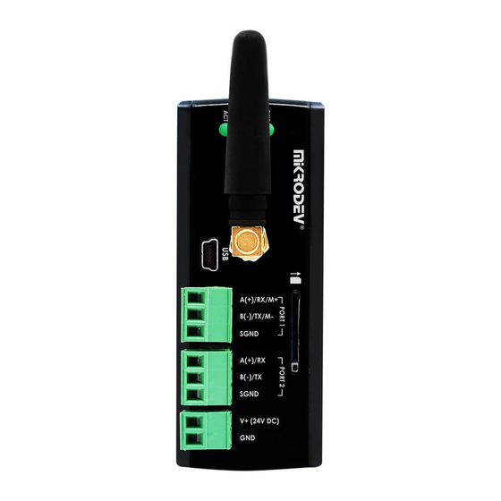
USB Configuration Port System LED M-Bus Port Connections Remote Connection LED Serial Port Ground Connection GSM or Wi-Fi Antenna Connection RS485 or RS232 Connections SIM Card Slot Device Power (V+) Connection Ethernet Port Device Power (V-) Connection MMS100 SERIES – HARDWARE MANUAL... -
Page 8: General Device Spesifications
1 Port RS485 / RS232* 1 Port Quad-Band GSM / GPRS Wireless 850/900/1800/1900 MHz Communication Wi-Fi IEEE 802.11 b/g/n USB Port 1 Port, Mini USB Type B Configuration Over TCP Eth/Wi-Fi/GSM *May differ on some models MMS100 SERIES – HARDWARE MANUAL... -
Page 9: Installation Information
First, the upper part of the device is mounted on the DIN rail. Then, with the help of the springs behind the device, when a lightly force is applied to the lower part, the device locates into the DIN rail easily and the montage is completed. Figure 2 Mounting Information MMS100 SERIES – HARDWARE MANUAL... - Page 10 DIN Rail Demountage To demount the device, firstly it is pulled from the bottom using flexibility of the spring, the device is removed from the DIN Rail and the demounting is completed. Figure 3 Demountage MMS100 SERIES – HARDWARE MANUAL...
-
Page 11: Connection Diagrams
CONNECTION DIAGRAMS 3.1 Supply Connection Supply: 9-36 VDC, Protected Power: <13 W Figure 4 Power Connection Diagram MMS100 SERIES – HARDWARE MANUAL... -
Page 12: M-Bus Port
3.2 M-Bus Port M-Bus Port Count: 1 Port Maximum Slave Counts: Data Bits: Stop Bits: Parity: None-Even-Odd Baudrate: 300 bps to 200 kbps Figure 5 M-BUS Port Input Connection Diagram MMS100 SERIES – HARDWARE MANUAL...
Need help?
Do you have a question about the MMS100 and is the answer not in the manual?
Questions and answers