
Subscribe to Our Youtube Channel
Related Manuals for MIKRODEV MDC100


Summary of Contents for MIKRODEV MDC100
- Page 1 MDC100 HARDWARE MANUAL MDC100 DLMS GATEWAY Series 07 / 2017 MIKRODEV_HM_MDC100_EN...
-
Page 2: Table Of Contents
CONTENTS MDC100 GENERAL INFORMATION ..............7 Physical Interfaces ..................7 General Device Spesifications ..............8 INSTALLATION INFORMATION................9 Rail Installation ..................9 CONNECTION DIAGRAMS ................11 Supply Connection ..................11 RS485 SERIAL PORT .................12 RS232 SERIAL PORT .................13 MDC100 – HARDWARE MANUAL... - Page 3 Figure 1 Connecter and Physical Interfaces ............... 7 Figure 2 Mounting ....................9 Figure 3 Demountage ....................10 Figure 4 Power Connection Diagram ................11 Figure 5 RS485 Input Connection Diagram ..............12 Figure 6 RS232 Input Connection Diagram ..............13 MDC100 – HARDWARE MANUAL...
- Page 4 DATA READOUT is used for reading. With this method, PROGRAMMING MODE commands can also be defined for unreadable OBIS codes. In this document, you can find information about the hardware specifications of Mikrodev MDC100 series devices. Please follow our website www.mikrodev.com...
- Page 5 MIKRODEV is one of the few companies in the world that has its own designed IEC 61131-3 compliant library for its programmable logic control devices. In addition, the open, flexible, programmable SCADA solution developed by MIKRODEV is also available to customers.
- Page 6 Make sure that the environment in which your device is being used is free of moisture, electric shock, vibration and dust. Pay attention to the supply voltage and the connections of the product. Mikrodev is not responsible for any issues due to power failure since there is no auxiliary supply (UPS) on the device.
- Page 7 MDC100 – HARDWARE MANUAL...
-
Page 8: Mdc100 General Information
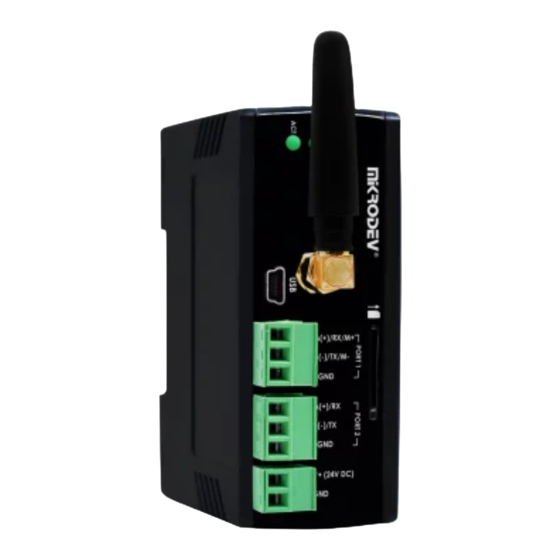
GSM or WIFI antenna Connection USB configuration port SIM card Slot Remote Connection Activity LED System LED POWER LED Ethernet port Factory Settings RS422 Connections RS485 Connections Rs232 TX-RX Connections RS-232 Nötr Connection DevicePower(V+) Connectin(+24V) Device Power (V-) Connection MDC100 – HARDWARE MANUAL... -
Page 9: General Device Spesifications
Storage Temperature -40 / +85 C Conditions Humidity 5..95 RH Ethernet Port 100 Mbit, MODBUS TCP Communication Ports RS485 RS232 GSM / GPRS Quad-Band Wireless 850/900/1800/1900 MHz Communication Wi-Fi USB port Configuration Over TCP Over ETH/Wi-Fi/GSM MDC100 – HARDWARE MANUAL... -
Page 10: Installation Information
DIN rail easily and the montage is completed. (See 16 A - 16 B) Figure 2 Mounting MDC100 – HARDWARE MANUAL... -
Page 11: Figure 3 Demountage
DIN Rail Demountage To demount the device, firstly it is pulled from the bottom using flexibility of the spring, the device is removed from the DIN Rail and the demounting is completed. Figure 3 Demountage MDC100 – HARDWARE MANUAL... -
Page 12: Connection Diagrams
CONNECTION DIAGRAMS 3.1 Supply Connection Supply: 12-36 VDC, Protected Power: < 13 W Figure 4 Power Connection Diagram MDC100 – HARDWARE MANUAL... -
Page 13: Rs485 Serial Port
3.2 RS485 SERIAL PORT RS485 port Count: Isolation: Galvanic Maximum Slave Counts: Communication Distance: 1000 m Data Bits: Stop Bits: Parity: None-Even-Odd Baudrate: 300 bps to 200 kbps Figure 5 RS485 Input Connection Diagram MDC100 – HARDWARE MANUAL... -
Page 14: Rs232 Serial Port
3.3 RS232 SERIAL PORT RS232 port Count: Communication Distance: 10 m Data Bits: Stop Bits: Parity: None-Even-Odd Baudrate: 300 bps to 200 kbps Figure 6 RS232 Input Connection Diagram MDC100 – HARDWARE MANUAL... - Page 15 MDC100 – HARDWARE MANUAL...
Need help?
Do you have a question about the MDC100 and is the answer not in the manual?
Questions and answers