Table of Contents
Advertisement
Quick Links
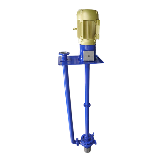
G2S
Line-Shaft Sump Pump
Part Number: _______________________________________
Serial Numbers: _____________________________________
These operating instructions contain fundamental information and precautionary notes.
Please read the manual thoroughly prior to installation of unit, electrical connection and
commissioning. It is imperative to comply with all other operating instructions referring to
components of individual units.
This manual shall always be kept close to the unit's location of operation or directly on the pump set.
INSTALLATION, OPERATION AND
MAINTENANCE INSTRUCTIONS
I-481
DEC 2016
ATEX REV.0
Inch Units
Advertisement
Table of Contents

Related Manuals for Carver Pump G2S


Summary of Contents for Carver Pump G2S
- Page 1 I-481 DEC 2016 Line-Shaft Sump Pump ATEX REV.0 Inch Units INSTALLATION, OPERATION AND MAINTENANCE INSTRUCTIONS Part Number: _______________________________________ Serial Numbers: _____________________________________ These operating instructions contain fundamental information and precautionary notes. Please read the manual thoroughly prior to installation of unit, electrical connection and commissioning.
- Page 2 This page left intentionally blank.
- Page 3 I-481 Line-Shaft Sump Pump December 2016 SERVICE RECORD PAGE Service No. ______________________ Model _________________________ Size and Type _______________ Customer Order No. ____________________________ Date Installed __________________________________ Installation Date Location Application PUMP RATING Capacity _____________________________________ Total Head ____________________________________ Suction Pressure ______________________________ Speed (RPM) __________________________________ Liquid pumped ________________________________ Temperature ___________________________________ Specific Gravity _______________________________ Viscosity ______________________________________...
- Page 4 I-481 Line-Shaft Sump Pump December 2016 NOTES ON INSPECTION AND REPAIRS INSPECTION DATE REPAIR TIME REPAIRS COST REMARKS...
-
Page 5: Table Of Contents
2. Sling Position for Moving Pumping TROUBLESHOOTING OPERATING Unit without Motor ........4 PROBLEMS ..........6 3. G2S Sectional Drawing ......19 4. Lineshaft Bearing Lube Variations ..... 20 MAINTENANCE ..........8 5. Shaft Coupling Detail ......... 21 A. Lubrication of Pump Bearings, Lineshaft 6. - Page 6 This page left intentionally blank.
-
Page 7: General Description And Safety
User CAUTION Instructions is believed to be reliable. In spite of all the efforts of Carver Pump Company to provide sound and These instructions must always be kept close all necessary information the content of this manual may to the product's operating location or directly appear insufficient and is not guaranteed by Carver with the product. -
Page 8: Parts Inventory Guide
Instructions attached directly to the machine, e.g. Arrow indicating the direction of rotation Carver Pump Company may ship an interchangeable part that is not identical in appearance or symbol. This is Markings for fluid connections must always be done only if the part has been improved. -
Page 9: Inspection And Storage
Carver Pump should come with the motor. and to the extent permitted by Carver Pump. Original spare parts and accessories authorized by Carver Pump The standard pump ball bearings are packed with ensure safety. -
Page 10: Handling
I-481 Line-Shaft Sump Pump December 2016 B. HANDLING. CAUTION Use a hoist with adequate lifting capacity. Do not pick up the complete unit by the motor, the pump shafts, or motor lifting eyes. If the pumping unit slips out of the sling arrangement, it may cause injury to personnel and/or damage to the pumping unit. -
Page 11: Piping
I-481 Line-Shaft Sump Pump December 2016 E. PIPING. All piping should be independently IV. OPERATION. supported near the pump so that pipe strain will not be transmitted to the pumping unit. A. PRE-START CAUTIONS. CAUTION DANGER All piping connections must be made with the Before activating the pumping unit, check to pipe in a freely supported state. -
Page 12: Starting The Pump
I-481 Line-Shaft Sump Pump December 2016 C. STARTING THE PUMP. similar to number stamped on the pump nameplate. 3. Check and record vibration. CAUTION 4. Check and record power input to the motor. Do NOT operate pumping unit against a closed E. - Page 13 5. Check oil temperature and adjust as high. necessary. 6. Incorrect impeller diameter. 6. Replace impeller or trim impeller to correct diameter. Consult with Carver Pump before trimming impeller. Vibration 1. Foundation bolting loose. 1. Torque bolting to proper values.
-
Page 14: Maintenance
10,000 hours afterwards. Ball bearings should be recorded for each pump to keep track of are lubricated at Carver Pump Company with Amoco maintenance which has been performed and to note Rykon Premium Grease No. 2EP or equivalent, non- operational problems. -
Page 15: Lubrication Of Motor
Lineshaft Bearings (63). The grease recommended for the ball bearings above is recommended and used by Carver Pump Company for sealed for life lineshaft bearings. After lineshaft bearings and oil seals (47A) are installed on shaft (6) put enough grease in the lineshaft bearings that it comes out the hole for the plug on the other side. -
Page 16: Service And Repair
All parts should be 2. Stop the pumping unit; refer to Section IV, thoroughly cleaned or replaced with new, if necessary. Paragraph E. Sealing faces should be perfectly clean. Carver Pump Company recommends that all O-rings and shims are only used once. WARNING... - Page 17 I-481 Line-Shaft Sump Pump December 2016 surface. If servicing motor or replacing coupling, 10. Remove bolts (601) from flange adaptor (85). loosen setscrews to remove coupling half and Remove backhead (11) from flange adaptor with motor coupling key from motor shaft. throttle bushing (63X) in backhead.
-
Page 18: Parts Inspection
I-481 Line-Shaft Sump Pump December 2016 Removal of Bearings. Disassembly of Lineshaft Coupling. (Refer to Figure NOTE NOTE DO NOT remove ball bearings (18) from shaft (6) unless the ball bearing needs replaced, if If the column is over ten feet long, there will be disturbed from position replace ball bearings a two-piece lineshaft. -
Page 19: Lineshaft Bearing Clearances
I-481 Line-Shaft Sump Pump December 2016 5. Inspect impeller and coupling keys for distortion b. Measure Inside Diameter (ID) of wear ring and push fit into keyways. The keys should be (7) in three places. square on all four edges. They should fit without c. -
Page 20: Reassembly Of Pump
I-481 Line-Shaft Sump Pump December 2016 Table 6. Enclosed Impeller Clearances Factory Standard Wear Ring Wear Ring Ordering Impeller Size Impeller Size Diametric Clearance Pump Size Size Front Size Back Code Front (Inches) Back (Inches) (Inches) (Inches) Minimum Maximum 2 x 1 x 11 2.750/2.749 2.762/2.760 .010 in. - Page 21 (608 and 610) until the bearing(s) already installed, be purchased from rotating element turns freely. Carver Pump Company. This will prevent the likelihood of lineshaft bearing(s) shattering due 19. Secure casing (1) with bolts (600) and washers to misalignment.
-
Page 22: Adjusting Impeller Clearance On Pump
I-481 Line-Shaft Sump Pump December 2016 23. Remove lifting eyes and replace with foundation Enclosed Impeller. To adjust impeller clearance on a bolts as applicable. pump equipped with an enclosed impeller use the following procedure: CAUTION If the impeller rubs the casing (1), adjust bearing cartridge (37) upward by loosening bolts (608 and 610) Use a hoist with adequate lifting capacity. -
Page 23: Motor
I-481 Line-Shaft Sump Pump December 2016 maximum to be sure arbor and impeller (2) are 10. Reassemble pump per Section VII, Paragraphs running square. D and E as needed. 5. Turn wearing surface of impeller (2) until a 63 G. MOTOR. The motor should be maintained in RMS or better finish is obtained. -
Page 24: Recommended Spare Parts List
I-481 Line-Shaft Sump Pump December 2016 Table 9. Recommended Spare Pump Parts List Item No. Part Name Item No. Part Name Bolt – Column/Bearing frame Wear ring (if equipped) Bolt – Base/Bearing frame Wear ring (if equipped) Bolt – Bearing frame/Motor Shaft sleeve (if equipped) Bolt –... -
Page 25: G2S Sectional Drawing
I-481 Line-Shaft Sump Pump December 2016 Figure 3. G2S Sectional Drawing... -
Page 26: Lineshaft Bearing Lube Variations
I-481 Line-Shaft Sump Pump December 2016 Sealed for Life External Flush External Lubrication Figure 4. Lineshaft Bearing Lube Variations... -
Page 27: Shaft Coupling Detail
I-481 Line-Shaft Sump Pump December 2016 Item Description Lower Shaft Upper Shaft Lineshaft Coupling Washer Tapered Pin Detail of Shaft Coupling for Pumps with Columns Over 10 Feet Long Figure 5. Shaft Coupling Detail Figure 6. Optional Wear Rings... -
Page 28: Optional Sleeve
I-481 Line-Shaft Sump Pump December 2016 Figure 7. Optional Sleeve Figure 8. Optional Oil Lubrication... - Page 29 I-481 Line-Shaft Sump Pump December 2016 This page left intentionally blank.
- Page 30 I-481 DEC 2016...
Need help?
Do you have a question about the G2S and is the answer not in the manual?
Questions and answers