Table of Contents
Advertisement
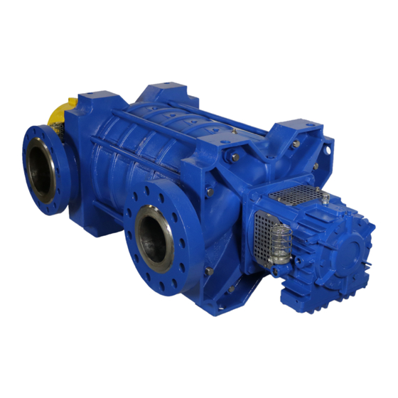
RS – Multi-Stage, Centrifugal Pump
Part Number: _______________________________________
Serial Numbers: _____________________________________
These operating instructions contain fundamental information and precautionary notes. Please read the manual
thoroughly prior to installation of unit, electrical connection and commissioning. It is imperative to comply with all
other operating instructions referring to components of individual units.
This manual shall always be kept close to the unit's location of operation or directly on the pump set.
INSTALLATION, OPERATION AND
MAINTENANCE INSTRUCTIONS
I-280
280 – 16.03.EN
Inch Units
For Units Built After December 2015
ATEX REV.0
Inch Units
ATEX
Advertisement
Table of Contents


Need help?
Do you have a question about the RSA and is the answer not in the manual?
Questions and answers