Table of Contents
Advertisement
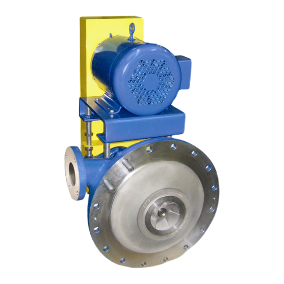
855 – Filtrate Pump
SAFETY, INSTALLATION, OPERATION AND
Part Number: _______________________________________
Serial Numbers: _____________________________________
These operating instructions contain fundamental information and precautionary notes. Please read the manual
thoroughly prior to installation of unit, electrical connection and commissioning. It is imperative to comply with all
other operating instructions referring to components of individual units.
This manual shall always be kept close to the unit's location of operation or directly on the pump set.
MAINTENANCE INSTRUCTIONS
I-855
855-15.04.EN
ATEX REV.0
Inch Units
Advertisement
Table of Contents
Troubleshooting

Related Manuals for Carver Pump 855 Series


Summary of Contents for Carver Pump 855 Series
- Page 1 I-855 855-15.04.EN 855 – Filtrate Pump ATEX REV.0 Inch Units SAFETY, INSTALLATION, OPERATION AND MAINTENANCE INSTRUCTIONS Part Number: _______________________________________ Serial Numbers: _____________________________________ These operating instructions contain fundamental information and precautionary notes. Please read the manual thoroughly prior to installation of unit, electrical connection and commissioning. It is imperative to comply with all other operating instructions referring to components of individual units.
- Page 2 NOTE: The 855 pumps are NOT supplied or Declared to ATEX Directive 94/9/EC. Person authorized to compile the technical documentation: Kurt Doren, Quality/ISO Manager, Carver Pump Company, 2415 Park Ave, Muscatine Iowa, USA 52761 Authorized Signature: Date: March 2015...
- Page 3 I-855 855 – Filtrate Pump 855-15.04.EN SERVICE RECORD PAGE Service No. ______________________ Model _________________________ Size and Type _______________ Customer Order No. ____________________________ Date Installed __________________________________ Installation Date Location Application PUMP RATING Capacity _____________________________________ Total Head ____________________________________ Suction Pressure ______________________________ Speed (RPM) __________________________________ Liquid pumped ________________________________ Temperature ___________________________________ Specific Gravity _______________________________ Viscosity ______________________________________...
- Page 4 I-855 855 – Filtrate Pump 855-15.04.EN NOTES ON INSPECTION AND REPAIRS INSPECTION DATE REPAIR TIME REPAIRS COST REMARKS...
-
Page 5: Table Of Contents
I-855 855 – Filtrate Pump 855-15.04.EN INSTALLATION, OPERATION AND MAINTENANCE INSTRUCTIONS TABLE OF CONTENTS SECTION/PARAGRAPH PAGE SECTION/PARAGRAPH PAGE GENERAL DESCRIPTION ....... 1 VII. INSTALLATION ..........10 A. General Information ........1 A. Location ............. 10 B. Machinery Directive 2006/42/EC ....1 B. - Page 6 I-855 855 – Filtrate Pump 855-15.04.EN TABLE OF CONTENTS - Continued LIST OF TABLES LIST OF ILLUSTRATIONS NUMBER TITLE PAGE NUMBER TITLE PAGE 1. Estimated Noise Characteristics ....7 1. Model 855-OH Pump ........4 2. Key Component Materials ......8 2.
-
Page 7: General Description
Instructions is believed to be reliable. In spite of all the and all necessary steps should be taken by the owner to efforts of Carver Pump Company to provide sound and assure compliance with such laws before operating the all necessary information the content of this manual may equipment. -
Page 8: Pump Identification
Arrow indicating the direction of rotation permitted after consultation with Carver Pump and to the extent permitted by Carver Pump. Original spare parts Markings for fluid connections must always be... -
Page 9: Scope Of Compliance
Where Carver Pump has supplied only the bare shaft Pumps handling fluids that are hazardous to personnel pump, the rating applies only to the pump. The party must be decontaminated prior to being worked on. -
Page 10: Non-Compliance With Safety Instructions
I-855 855 – Filtrate Pump 855-15.04.EN moving vane-type meters should III. EQUIPMENT DESCRIPTION. grounded nor held during measurements. A. PUMP HISTORY. Do NOT use test equipment known to be damaged or in poor condition. The Filtrate Pump line was designed in the late 1950’s request large Original... -
Page 11: Effects Of Fluids
I-855 855 – Filtrate Pump 855-15.04.EN thereby the head/flow conditions delivered by the pump. The bearing frame (19) is connected to the motor plate This pump is also built in a close coupled (direct drive) with threaded rods (632) and jam nuts (616). The motor configuration, the Model 855-CC, for use when the v- is bolted to the motor plate with bolts (604) and hex nuts drive feature is not required. -
Page 12: Changing Pump Speed
(2400 rpm). operation at some viscosity other than that for which the Dimensions and diameters are reference and given in pump was originally designed, check with Carver Pump inches. Company. D. EFFECTS OF SPECIFIC GRAVITY. The capacity... -
Page 13: Estimated Noise Characteristics
I-855 855 – Filtrate Pump 855-15.04.EN Table 1. Estimated Noise Characteristics Estimated Sound Pressure Level L pA (dB)* Rated Power Input Pump with Motor Pump Only PN (kw) 1750 1450 1750 1450 61.5 58.5 63.5 60.5 65.5 62.5 68.5 65.5 57.5 57.5 58.5... -
Page 14: Key Component Materials
I-855 855 – Filtrate Pump 855-15.04.EN Table 2. Key Component Materials Component Material Specification Bearing Frame Ductile Iron ASTM A536 Rubber Natural Rubber Lined C.I. ASTM A48, Class 30 Casing CD4MCu ASTM A890 Cast Iron ASTM A48, Class 30 Cast Iron ASTM A48, Class 30 Impeller CD4MCu... -
Page 15: Inspection And Storage
B. PACKING FOR RETURN. If the pumping unit is 2. It has been installed but operation is delayed sent back to Carver Pump Company for repair, drain the pending completion of construction. unit, and re-seal all flanges and connections that were 3. -
Page 16: Installation
I-855 855 – Filtrate Pump 855-15.04.EN VII. INSTALLATION. A. LOCATION. The pump assembly should be located in an area that will permit periodic inspection and maintenance. Head room and access should be provided and all units should be installed in a dry location with adequate drainage. -
Page 17: Pre-Installation Procedures
I-855 855 – Filtrate Pump 855-15.04.EN C. PRE-INSTALLATION PROCEDURES. CAUTION CAUTION All piping connections must be made with the pipe in a freely supported state. Do not apply Use a hoist with adequate lifting capacity. See vertical or side pressure to align the piping with pump nameplate for weights. -
Page 18: Direction Of Rotation
I-855 855 – Filtrate Pump 855-15.04.EN G. DIRECTION OF ROTATION. Direction of rotation B. PRIMING. Dry running a centrifugal pump can for 855OH pumps is clockwise as viewed from belt end result in extensive damage and possible seizing. It is, of pump shaft. -
Page 19: Stopping The Pump
I-855 855 – Filtrate Pump 855-15.04.EN 2. Check mechanical seals or packing rings for F. INDEFINITE SHUTDOWN. leakage. Stop the pumping unit per Section VIII, Paragraph E. 3. Check for adequate lubricating liquid flow to the Remove casing plug to drain casing. Drain all piping if seal or packing. -
Page 20: Pumping Unit Troubleshooting
Section VIII, Paragraph pressure. against design head. conditions; Consult local distributor or Carver Pump Company. 2. Speed to low, motor 1. Correct motor speed. speed incorrect, belts 2. Adjust belt tension. slip, or line voltage to 3. - Page 21 (check pump Decrease speed if nameplate). driver remains overloaded. 3. Same as 2 under 1. Same as 2 under pump “Pump Discharge discharge pressure Pressure Excessive.” excessive. 4. Wrong port width. 1. Consult Carver Pump Company specifying exact operating conditions.
-
Page 22: Maintenance
I-855 855 – Filtrate Pump 855-15.04.EN A. LUBRICATION OF PUMP BEARINGS. The ball MAINTENANCE. bearings installed "Greased-For-Life". Always replace the roller bearings when disassembling unit for Generally the pump does not need continuous seal service. supervision. The pump should always run quietly and smoothly, without vibration. -
Page 23: Service And Repair
CAUTION the pumping unit. Factory authorized parts must be used to safely maintain your Carver Pump. When pump is handling hazardous fluid, extreme care must be taken to ensure safety of NOTE personnel when attempting to drain pump and piping before disconnecting the pumping unit. -
Page 24: Disassembly Of Pump
B. DISASSEMBLY OF PUMP. The instructions that follow are an aid for properly trained personnel to NOTE service your Carver Pump. Refer to Figures 15 and 16 Refer to cartridge seal (90*), refer to vendor to locate the pump parts by item number and parts list instructions for proper mechanical seal removal Table 8. -
Page 25: Parts Inspection
I-855 855 – Filtrate Pump 855-15.04.EN NOTE NOTE Take special care during disassembly with the If ball bearings are disturbed from position mechanical seal rotary and stationary elements replace with new. when removing the casing off the shaft. 15. If desired, pull ball bearing (18) from shaft (6). 6. -
Page 26: Reassembly Of Pump
Handle lip seal (169) with care. Mishandling assemble your Carver Pump. Refer to Figures 15 and could damage faces of the lip seal. 16 to locate the pump parts by item number and parts list Table 8. - Page 27 I-855 855 – Filtrate Pump 855-15.04.EN a. Impeller clearance should be .015 to .020”. 10. For units with packing (180*), install the lantern ring (29*) on the shaft (6) sliding the lantern ring b. If the impeller (3) needs shimmed towards back near the slinger (40).
-
Page 28: Replacement Of Packing
Standard shaft diameter is 32mm (1 1/4”). keep the motor and pump shafts parallel. c. Pre-cut sets of packing and lantern rings are available for stock from Carver Pump 29. Install motor (200) on motor plate (23), secure Company motor to motor plate with bolts (604) and hex 2. -
Page 29: Replacement Of Mechanical Seal
I-855 855 – Filtrate Pump 855-15.04.EN evenly. Final adjustments should be made by rotating gland hex nuts one flat at a time. NOTE If stuffing box is hot to the touch (approximately 65°C or 150°F), there is not enough flush water entering the stuffing box. -
Page 30: Belt Installation And Adjustment
I-855 855 – Filtrate Pump 855-15.04.EN Mechanical Seal Installation G.1 General 1. Lubricate and install sleeve O-ring (89*) onto Belt driven pump sets must always be earthed shaft (6). (electrically grounded). The condition of the belts must be checked regularly. After fastening the unit to the tank NOTE flange and connecting the piping, the belt drive must be thoroughly checked and the belts re-tensioned, if... -
Page 31: Belt Tensioning
I-855 855 – Filtrate Pump 855-15.04.EN G.4 Belt Installation and Maintenance 3. The belts (276) must be fitted by hand without using force. For this purpose, reduce the distance between the sheaves (277) by moving CAUTION the motor plate (23) downwards. Pulling the belts under tension over the edges of the Do not operate the pump without belt guards in sheaves or using metal tools can cause invisible... -
Page 32: Optional Swing-Out Mount Installation
Use a hoist with adequate lifting capacity; refer trained personnel to install an optional swing-out mount to Section VII, Paragraph B, for lifting the on your Carver Pump. These instructions refer to Figure complete unit. 16 as an example. The tank flange detail is shown in Figure 17. -
Page 33: Motor
I-855 855 – Filtrate Pump 855-15.04.EN Template Holes Figure 13. Adjuster Bolt (Closed position) for Tank Flange Figure 14. Adjuster Bolt (Open position) Figure 12. Drilling Tank Flange for Swing-out MOTOR. The motor should be maintained in XII. PARTS LISTS AND DRAWINGS. accordance with the manufacturer’s instructions. -
Page 34: Parts List
I-855 855 – Filtrate Pump 855-15.04.EN Table 8. Parts List Item Number Description Item Number Description Casing 131D Belt Guard Impeller 131E Cover, Belt Guard Shaft 131G Shaft Guard Suction Cover Bracket, Belt Guard Shaft Sleeve Lip Seal Impeller Shim (not shown) *176 Snap Ring - Adjuster Bolt Ball Bearing... -
Page 35: Recommended Spare Parts
I-855 855 – Filtrate Pump 855-15.04.EN Table 9. Recommended Spare Parts List Item Number Description Item Number Description Impeller Key, Pump Bushing Shaft Sleeve Spacer - Mechanical Seal Impeller Shim (set) Gasket, Frame - Cap (set) Ball Bearing Gasket, Casing - Suction Gland Gasket, Suction - Tank Ball Bearing (Impeller End) -
Page 36: Sectional Assembly - Close-Coupled Pump (Shown With Mechanical Seal)
I-855 855 – Filtrate Pump 855-15.04.EN Figure 15. Sectional Assembly – Close-Coupled Pump (Shown with Mechanical Seal) -
Page 37: Sectional Assembly With Overhead Drive (Shown With Packing)
I-855 855 – Filtrate Pump 855-15.04.EN Figure 16. Sectional Assembly with Overhead Drive (Shown with Packing) -
Page 38: Optional Swing-Out Assembly
I-855 855 – Filtrate Pump 855-15.04.EN Figure 17. Optional Swing-out Assembly... -
Page 39: Model 855 Tank Mounting Flange
I-855 855 – Filtrate Pump 855-15.04.EN Figure 18. Model 855 Tank Mounting Flange... -
Page 40: Model 855 Universal Discharge Flange
I-855 855 – Filtrate Pump 855-15.04.EN Figure 19. Model 855 Universal Discharge Flange... - Page 41 I-855 855 – Filtrate Pump 855-15.04.EN This page intentionally left blank.
- Page 42 2415 Park Avenue, Muscatine, IA 52761 Phone: 563.263.3410 www.carverpump.com 855 Filtrate Pump IOM 855 – 15.04.EN ATEX REV.0...
Need help?
Do you have a question about the 855 Series and is the answer not in the manual?
Questions and answers