Table of Contents
Advertisement
Quick Links
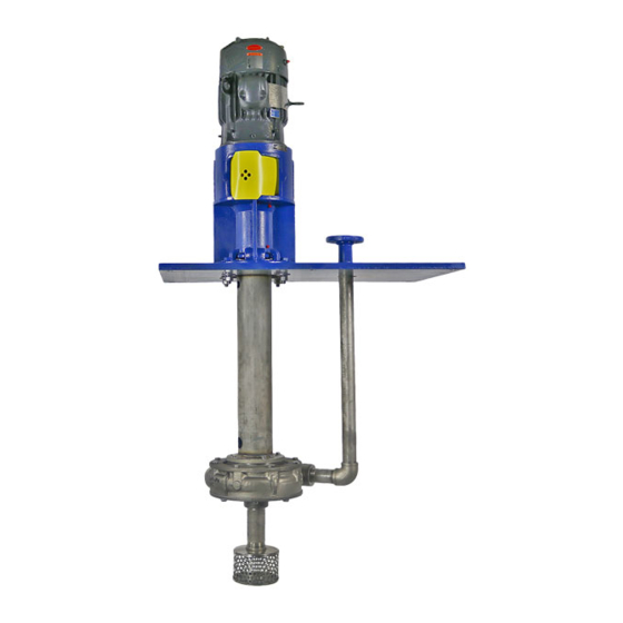
G2C
Cantilevered Sump Pump
Part Number: _______________________________________
Serial Numbers: _____________________________________
These operating instructions contain fundamental information and precautionary notes. Please read the manual
thoroughly prior to installation of unit, electrical connection and commissioning. It is imperative to comply with all other
operating instructions referring to components of individual units.
This manual shall always be kept close to the unit's location of operation or directly on the pump set.
INSTALLATION, OPERATION AND
MAINTENANCE INSTRUCTIONS
I-461
461-15.02.EN
ATEX REV.0
Inch Units
Advertisement
Table of Contents

Related Manuals for Carver Pump G2C


Summary of Contents for Carver Pump G2C
- Page 1 I-461 461-15.02.EN ATEX REV.0 Inch Units Cantilevered Sump Pump INSTALLATION, OPERATION AND MAINTENANCE INSTRUCTIONS Part Number: _______________________________________ Serial Numbers: _____________________________________ These operating instructions contain fundamental information and precautionary notes. Please read the manual thoroughly prior to installation of unit, electrical connection and commissioning. It is imperative to comply with all other operating instructions referring to components of individual units.
- Page 2 I-461 Cantilevered Sump Pump 461-15.02.EN This page left intentionally blank.
- Page 3 I-461 Cantilevered Sump Pump 461-15.02.EN SERVICE RECORD PAGE Service No. ______________________ Model _________________________ Size and Type _______________ Customer Order No. ____________________________ Date Installed __________________________________ Installation Date Location Application PUMP RATING Capacity _____________________________________ Total Head ____________________________________ Suction Pressure ______________________________ Speed (RPM) __________________________________ Liquid pumped ________________________________ Temperature ___________________________________ Specific Gravity _______________________________ Viscosity ______________________________________...
- Page 4 I-461 Cantilevered Sump Pump 461-15.02.EN NOTES ON INSPECTION AND REPAIRS INSPECTION DATE REPAIR TIME REPAIRS COST REMARKS...
-
Page 5: Table Of Contents
Unit without Motor ........4 TROUBLESHOOTING OPERATING 3. Sling Position for Moving Pumping Unit..4 PROBLEMS ..........6 4. G2C (1521 Frame) Sectional Drawing ..20 5. G2C (1532 Frame) Sectional Drawing ..21 MAINTENANCE ..........7 6. Optional Wear Rings ........22 A. - Page 6 I-461 Cantilevered Sump Pump 461-15.02.EN This page left intentionally blank.
-
Page 7: General Description And Safety
User CAUTION Instructions is believed to be reliable. In spite of all the efforts of Carver Pump Company to provide sound and These instructions must always be kept close all necessary information the content of this manual may to the product's operating location or directly appear insufficient and is not guaranteed by Carver with the product. -
Page 8: Parts Inventory Guide
Instructions attached directly to the machine, e.g. Arrow indicating the direction of rotation Carver Pump Company may ship an interchangeable part that is not identical in appearance or symbol. This is Markings for fluid connections must always be done only if the part has been improved. -
Page 9: Inspection And Storage
Carver Pump should come with the motor. and to the extent permitted by Carver Pump. Original spare parts and accessories authorized by Carver Pump The pump ball bearings are packed with grease which ensure safety. -
Page 10: Handling
I-461 Cantilevered Sump Pump 461-15.02.EN B. HANDLING. CAUTION Use a hoist with adequate lifting capacity. Do not pick up the complete unit by the motor or the pump shafts or motor lifting eyes. If the pumping unit slips out of the sling arrangement, it may cause injury to personnel and/or damage to the pumping unit. -
Page 11: Pre-Installation Procedures
I-461 Cantilevered Sump Pump 461-15.02.EN D. PRE-INSTALLATION PROCEDURES. CAUTION 1. Check the pump foundation and confirm the bolting surface is flat and the bolt pattern is Connection to the power supply must be correct. effected by a trained electrician only. Check available main voltage against the data on the 2. -
Page 12: Priming
I-461 Cantilevered Sump Pump 461-15.02.EN B. PRIMING. Dry running a centrifugal pump can cause remedy refer result in extensive damage and possible seizing. It is, troubleshooting in Section V or consult Carver therefore, imperative that the pump be primed prior to Pump Company. - Page 13 5. Check oil temperature and adjust as high. necessary. 6. Incorrect impeller diameter. 6. Replace impeller or trim impeller to correct diameter. Consult with Carver Pump before trimming impeller. Vibration 1. Foundation bolting loose. 1. Torque bolting to proper values.
-
Page 14: Maintenance
10,000 hours afterwards. Ball bearings should be recorded for each pump to keep track of are lubricated at Carver Pump Company with Amoco maintenance which has been performed and to note Rykon Premium Grease No. 2EP or equivalent, non- operational problems. -
Page 15: Lubrication Of Motor
I-461 Cantilevered Sump Pump 461-15.02.EN Table 2. Recommended Torque Values (ft-lbs) CAUTION Bolt Size Material Over greasing creates heat and is the cause of Steel (or 316 Stainless many problems requiring repair. DO NOT Composite otherwise noted) Steel OVER GREASE. ¼”-20 1. -
Page 16: Service And Repair
B. DISASSEMBLY OF PUMP. Equipment, for proper tooling during disassembly and assembly. Refer to appropriate sectional drawing for G2C, 1521 FRAME (Cantilevered). (Refer to Figure 4 location of parts followed by an item number. and Table 7) Disassemble the pumping unit using the... - Page 17 20. Remove bearing spring (449). 4. Remove foundation bolts from base (23). Insert G2C, 1532 FRAME (Cantilevered). (Refer to Figure 5 one lifting eye onto each corner of the base bolt and Table 7) Disassemble the pumping unit using the holes.
-
Page 18: Parts Inspection
I-461 Cantilevered Sump Pump 461-15.02.EN NOTE 2. Inspect casing for pitting, scoring, and erosion. The inside of the casing should be free of any pits or grooves. Replace the casing if any of Impeller bolt (26) has right handed threads. these defects are present. -
Page 19: Enclosed Impeller Clearances
I-461 Cantilevered Sump Pump 461-15.02.EN b. Measure Inside Diameter (ID) of wear ring If difference between the high reading of the (7) in three places. ID of the wear ring (7X) and the low reading of the OD of the impeller (2) hub exceeds c. -
Page 20: Reassembly Of Pump
9. Install bearing housing assembly and shaft (6) onto base (23) and secure with bolts (602), G2C, 1521 FRAME (Cantilevered). (Refer to Figure 4 washers (630 and 631), and nuts (620). and Table 7) Reassemble the pumping unit using the following procedure: 10. - Page 21 VI, Paragraphs A, B, C, and D. 13. Install bearing housing assembly and shaft (6) G2C, 1532 FRAME (Cantilevered). (Refer to Figure 5 into column (101) and secure with bolts (602), and Table 7) Reassemble the pumping unit using the washers (630 and 631), and nuts (620).
-
Page 22: Adjusting Impeller Clearance On Pump
I-461 Cantilevered Sump Pump 461-15.02.EN G2C, 1532 FRAME (Cantilevered, Enclosed and CAUTION Semi-Open Impeller). Use a hoist with adequate lifting capacity. Enclosed Impeller. To adjust impeller clearance on a pump equipped with an enclosed impeller use the 21. Hoist motor to installation site. Place motor in... -
Page 23: Motor
I-461 Cantilevered Sump Pump 461-15.02.EN Table 6. Impeller/Wear Ring Matching Materials 7. Mount suction cover (9) with new wear ring (7) installed in a lathe. Indicate male rabbet to within 0.002 T.I.R. maximum. IMPELLER MATERIAL WEAR RING MATERIAL 8. Bore wear ring (7) to within specified tolerance All Iron &... -
Page 24: Parts Lists And Drawings
I-461 Cantilevered Sump Pump 461-15.02.EN for this pumping unit. Figures 4 or 5 are the sectional VIII. PARTS LISTS AND DRAWINGS. assembly drawings. This section contains listings of parts and corresponding drawings. Table 8 notes the recommended spare parts Table 7. Pump Parts List Item No. - Page 25 I-461 Cantilevered Sump Pump 461-15.02.EN Table 8. Recommended Spare Pump Parts List Item No. Part Name Item No. Part Name O-ring (Bearing Cap – 1532) Impeller (2 year spare) Wear ring (if equipped) Snap ring Snap ring – Bearing Holder (1532) Shaft sleeve (if equipped) Upper ball bearing Bearing spring (1521)
- Page 26 I-461 Cantilevered Sump Pump 461-15.02.EN Figure 4. G2C (1521 Frame) Sectional Drawing...
- Page 27 I-461 Cantilevered Sump Pump 461-15.02.EN Figure 5. G2C (1532 Frame) Sectional Drawing...
- Page 28 I-461 Cantilevered Sump Pump 461-15.02.EN Figure 6. Optional Wear Rings Figure 7. Optional Sleeve...
- Page 29 This page left intentionally blank.
- Page 30 2415 Park Avenue, Muscatine, IA 52761 Phone: 563.263.3410 www.carverpump.com G2C Cantilevered Sump Pump IOM 461-15.02.EN...
Need help?
Do you have a question about the G2C and is the answer not in the manual?
Questions and answers