Table of Contents
Advertisement
Quick Links
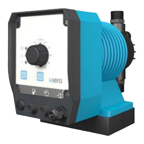
Solenoid diaphragm pump
Series R/RS 204.1
Operating Instructions
Product:
Solenoid diaphragm pump
R 204.1 – 0,4 e
Type:
R 204.1 – 1,2 e
R 204.1 – 2,4 e
R 204.1 – 6,0 e
R 204.1 – 7,0 e
R 204.1 – 10 e
R 204.1 – 14 e
R 204.1 – 25 e
R 204.1 – 30 e
R 204.1 – 35 e
Product:
Self ventilating
Solenoid diaphragm pump
RS 204.1 – 0,4 e
Type:
RS 204.1 – 1,2 e
RS 204.1 – 2,4 e
RS 204.1 – 6,0 e
RS 204.1 – 7,0 e
RS 204.1 – 10 e
RS 204.1 – 14 e
RS 204.1 – 25 e
RS 204.1 – 30 e
RS 204.1 – 35 e
Please state here the exact type and serial
number of your pump.
(can be read off the type plate on the pump)
Type:
Serial No.:
These data are important in case of queries or for ordering
spare and wearing parts and must absolutely be stated.
Manufacturer:
Seybert & Rahier
GmbH + Co. Betriebs-KG
sera-Straße 1
34376 Immenhausen
Germany
Tel. +49 5673 999-00
Fax. +49 5673 999-01
www.sera-web.com
info@sera-web.com
TA 416 Rev. 11 en 04/2013
Subject to technical modifications!
CAUTION !
Keep the operating instructions for future application!
www.sera-web.com
1
Advertisement
Table of Contents

Related Manuals for Sera R 204.1 Series


Summary of Contents for Sera R 204.1 Series
- Page 1 These data are important in case of queries or for ordering spare and wearing parts and must absolutely be stated. Manufacturer: Seybert & Rahier GmbH + Co. Betriebs-KG sera-Straße 1 34376 Immenhausen Germany Tel. +49 5673 999-00 CAUTION ! Fax. +49 5673 999-01 Keep the operating instructions for future application! www.sera-web.com...
-
Page 2: Table Of Contents
Components of the solenoid diaphragm pump ..8 10.4 Stroke length adjustment ........31 R 204.1 ..............8 10.5 Stroke frequency adjustment ......... 32 RS 204.1..............9 10.6 Configuring the level input ........32 TA 416 Rev. 11 en 04/2013 www.sera-web.com Subject to technical modifications! - Page 3 13.7 Shut-down ............44 13.8 Disassembly ............44 13.9 Disposal ..............44 Shut-down ............44 Disposal ..............44 15.1 Dismantling and transport ........44 15.2 Complete disposal ..........44 TA 416 Rev. 11 en 04/2013 Subject to technical modifications! www.sera-web.com...
-
Page 4: General
Operating Instructions Type plate General Before commissioning and during operation of the sera – so- Each sera solenoid diaphragm pump is factory provided with a type plate. The following information can be found on this lenoid diaphragm pump the respective regulations valid at the type plate. -
Page 5: Materials
ISO 9001:2008. knowledge required it is to be trained and instructed according- The sera solenoid diaphragm pump complies with the valid ly. If required such a traning can be carried out by the manu- safety requiremens and accident prevention regulations. -
Page 6: Safety Conscious Working
3.10 Intended use The safety instructions specified in this operating manual, the The sera – diaphragm pump is only to be deployed according national regulations for accident prevention, the safety regula- tions for the pumped medium valid at the place of installation... -
Page 7: Transport And Intermediate Storage
Operating Instructions Transport and intermediate storage General Before shipment sera - products are checked for proper condi- tion and functioning. The customer has to check the product for transport damage immediately aftr receipt. Any damage detected is to be report- ed immediately to the carrier and the supplier. -
Page 8: Components Of The Solenoid Diaphragm Pump
Electronics with operating panel Pressure valve Pump body (PVC- design) Assembly pump Motor housing with stroke magnet Suction valve Pump body (FRP- design) Fig. 02 Overview of the components R 204.1 TA 416 Rev. 11 en 04/2013 www.sera-web.com Subject to technical modifications! - Page 9 Pressure valve Pump body (PVC, PP, PVDF- design) Assembly pump Motor housing with stroke magnet Suction valve Pump body (FRP- design) Fig. 03 Overview of the components RS 204.1 TA 416 Rev. 11 en 04/2013 Subject to technical modifications! www.sera-web.com...
-
Page 10: Technical Specifications
Operating Instructions Technical specifications Dimensions R 204.1 Disign: PP- and. PVDF-FRP (...-1,2e until ...-14e) Disign: PVC, 1.4571 (and PP- and. PVDF-FRP ...-25e until ...-35e) View X Fig. 04 Dimensions R204.1 TA 416 Rev. 11 en 04/2013 www.sera-web.com Subject to technical modifications! - Page 11 Centre of valve thread (FRP-design) Centre of valve thread PB (FRP-design) PB (FRP-design) Pump body Stroke a.o. Dimensions for fas- see Fig. 04 mechanism tening of the pump TA 416 Rev. 11 en 04/2013 Subject to technical modifications! www.sera-web.com...
-
Page 12: Dimensions Rs 204.1
Operating Instructions Dimensions RS 204.1 Disign: PP- and. PVDF-FRP (...-6,0e until ...-14e) Disign: PVC, PP, PVDF (and PP- and. PVDF-FRP ...-25e until ...-35e) View X Fig. 05 Dimensions RS 204.1 TA 416 Rev. 11 en 04/2013 www.sera-web.com Subject to technical modifications! - Page 13 Centre of valve thread (FRP-design) Centre of valve thread PB (FRP-design) PB (FRP-design) PB (PVC, PP, PVDF- design) Stroke a.o. Dimensions for fas- see Fig. 05 mechanism tening of the pump TA 416 Rev. 11 en 04/2013 Subject to technical modifications! www.sera-web.com...
-
Page 14: Technical Data
Linear dosing range at a stroke length between 20% and 100% With the first suctioning, the stroke length has to be set to 100 % and the vent valve has to be opened TA 416 Rev. 11 en 04/2013 www.sera-web.com Subject to technical modifications! - Page 15 100 Ω R/RS 204.1-... max. 1,0 A 55 ms max. 15V DC, 50 mA IP 65 Circuit break- external supply max. 30V DC, 350 mA Table. 08 Electronics data TA 416 Rev. 11 en 04/2013 Subject to technical modifications! www.sera-web.com...
-
Page 16: Usable Stroke Length Range With Self-Ventilation
The dosing pump sucks independently between diagram value and 100 % of the stroke length. The diagram describes the operating range of the stroke length of pump type RS. TA 416 Rev. 11 en 04/2013 www.sera-web.com Subject to technical modifications! - Page 17 The diagram describes the operating range of the stroke length of pump type RS. CAUTION! Note the usable stroke length acc. to the preceding diagrams. Priming problems may arise if these values are fallen below. TA 416 Rev. 11 en 04/2013 Subject to technical modifications! www.sera-web.com...
-
Page 18: Functional Description
R/RS 204.1 General 7.2.1 Assembly pump / Motor housing sera solenoid diaphragm pumps R/RS 204.1 are self-priming and run-dry safe oscillating displacement pumps that are char- Function acterised by high tightness of the dosing head. The liquid is conveyed by a deformable drive diaphragm. -
Page 19: Pump Body
Open vent screw with great caution and perform max. 1 turn. Take care that the tightness of the thread is still guaranteed. ACHTUNG ! The vent screw must always be closed during the driving process. TA 416 Rev. 11 en 04/2013 Subject to technical modifications! www.sera-web.com... -
Page 20: Suction / Pressure Valve
Vent valve Solenoid valve Check valve Hose nozzle Fig. 13 Double valves, for evample. PVDF-FRP Return line Fig. 14 Vent valve, controllable TA 416 Rev. 11 en 04/2013 www.sera-web.com Subject to technical modifications! -
Page 21: Assembly / Installation
The pump is designed for operation in non-hazardous ar- eas! CAUTION ! Mount the solenoid diaphragm pump in such a way that leaking medium cannot cause any damage. TA 416 Rev. 11 en 04/2013 Subject to technical modifications! www.sera-web.com... -
Page 22: Provide Overpressure Protection
If the permissible operating pressure is exceeded and the pump is not equipped with an overpressure protection the Shut-off valve pump and the piping may be damaged. Suction line Fig. 17 System with (external) overflow valve TA 416 Rev. 11 en 04/2013 www.sera-web.com Subject to technical modifications! -
Page 23: Prevent A Backflow Of The Pumped Medium
Suction line Shut-off valve a backflow from the main pipe is not prevented. Fig. 19 Installing a pressure keeping valve CAUTION ! Note / avoid chemical reactions during a backflow. TA 416 Rev. 11 en 04/2013 Subject to technical modifications! www.sera-web.com... -
Page 24: How To Ensure An Gas-Free Suction
The delivery flow may be interrupted if air enters the suc- Return line tion line! Suction lance / Suction line Foot valve Container Fig. 20 Installing a ventilation valve TA 416 Rev. 11 en 04/2013 www.sera-web.com Subject to technical modifications! -
Page 25: How To Avoid An Emptying Of The Suction Line
If contaminations are not removed this may result in mal- functions of the pump and the system. Foot valve Container Fig. 22 Avoiding an emptying of the suction line TA 416 Rev. 11 en 04/2013 Subject to technical modifications! www.sera-web.com... -
Page 26: Suction Via A Siphon Pipe
Return line Container Shut-off valve Suction lance / Suction line Foot valve sera Fig. 24 Installing a siphon tank ( - fitting) Shut-off valve Suction line Fig. 26 Installation self ventilating solenoid diaphragm pump TA 416 Rev. 11 en 04/2013 www.sera-web.com... -
Page 27: Damping Of The Pulsation
Container Shut-off valve Suction line Suction line Fig. 27 Installing a pulsation damper (I) Shut-off valve Pulsation damper (suction side) Drain cock Fig. 29 Installing a pulsation damper (III) TA 416 Rev. 11 en 04/2013 Subject to technical modifications! www.sera-web.com... -
Page 28: Electrical Connections
CAUTION ! Undamped acceleration forces may lead to the following Electric supply faults / damage: The sera – magnetic diaphragm pump is delivered ready for delivery rate fluctuations installation. Standard delivery includes a 2m power cable with dosing errors Euro plug. The standard version R 204.1 of the dosing pump pressure serges is designed for an operating voltage range of 100 –... -
Page 29: Connecting The Control Cables
The digital inputs (pulse and external stop) can not only be switched by a potential-free contact signal (see Fig. 33) but also directly via a control voltage signal (e.g. 24V DC). TA 416 Rev. 11 en 04/2013 Subject to technical modifications! www.sera-web.com... -
Page 30: Pulse Input
Fig. 36 (Jack for level input) Suction lances that are compatible with types R/C 203 or C 408.1/409.1 can be connected to the pump using an adapter plug M8/M12, 3-pin (Item No. 90025005). TA 416 Rev. 11 en 04/2013 www.sera-web.com Subject to technical modifications! -
Page 31: Operation
LED lights steadily. If the level monitoring is connected, the dry run is indicated by a flashing red LED. In case of type RS 204.1, the red LED lights also when the vent valve opens. TA 416 Rev. 11 en 04/2013 Subject to technical modifications! www.sera-web.com... -
Page 32: Stroke Frequency Adjustment
Configuration of the level input can only be performed while the pump is switched off. Pump is ready to run CAUTION ! Stroke frequency can only be changed while the pump is switched off. TA 416 Rev. 11 en 04/2013 www.sera-web.com Subject to technical modifications! -
Page 33: Venting Settings (Only With Rs 204.1)
After having removed the ex- ternal stop signal, the pump will vent for the preset time. For deactivating the mode, please see the description in Chap- ter 10.7.4. TA 416 Rev. 11 en 04/2013 Subject to technical modifications! www.sera-web.com... -
Page 34: Venting After Switching On The Pump
“Venting after switching on” is activated, programming is com- pleted and the pump starts venting! If necessary, again switch off the pump using the STOP/START key. TA 416 Rev. 11 en 04/2013 www.sera-web.com Subject to technical modifications! -
Page 35: Switching Off The Venting
For the tightening torques of the fixing screws, please see Chapter 8.1 “Installation”. Repairs on the stroke mechanism may only be performed by sera. TA 416 Rev. 11 en 04/2013 Subject to technical modifications! www.sera-web.com... -
Page 36: Spare And Wearing Parts
Pressure valve (kit) Pump body Item Designation Pressure valve (incl. o-rings) Pump body kit (1.4571-, PVC-design) Item Designation Diaphragm kit Cheese head screw(s) Item Designation Disk(s) Drive diaphragm Pump body Insert TA 416 Rev. 11 en 04/2013 www.sera-web.com Subject to technical modifications! -
Page 37: Solenoid Diaphragm Pump R 204.1-25E
Pressure valve (kit) Item Designation Pump body kit (1.4571-, PVC-design) Pressure valve (incl. o-rings) Item Designation Cheese head screw(s) Diaphragm kit Disk(s) Item Designation Pump body Drive diaphragm Insert TA 416 Rev. 11 en 04/2013 Subject to technical modifications! www.sera-web.com... -
Page 38: Solenoid Diaphragm Pump Rs 204.1-0,4E
Pump body kit (PVC, PP, PVDF-design) Item Designation Diaphragm kit Cheese head screw(s) Item Designation Disk(s) Drive diaphragm Pump body Insert Automatic ventilation device kit Item Designation Automatic ventilation device (incl. o-ring) TA 416 Rev. 11 en 04/2013 www.sera-web.com Subject to technical modifications! -
Page 39: Solenoid Diaphragm Pump Rs 204.1-25E
Pressure valve (incl. o-rings) Item Designation Cheese head screw(s) Diaphragm kit Disk(s) Item Designation Pump body Drive diaphragm Insert Automatic ventilation device kit Item Designation Automatic ventilation device (incl. o-ring) TA 416 Rev. 11 en 04/2013 Subject to technical modifications! www.sera-web.com... -
Page 40: Changing Working Diaphragm
(avoid contact with it) and dis- pose of it in an environmentally compatible way. This measure is also necessary if the solenoid diaphragm pump should be returned for repair. TA 416 Rev. 11 en 04/2013 www.sera-web.com Subject to technical modifications! -
Page 41: Fault Analysis And Corrective Action
Fault analysis and corrective action (see Fig. 43) sera - products are sophisticated technical products which are only shipped after having been thoroughly tested and checked at our factory. Should there be any faults, these can be detected and rectified easily and quickly if the steps in Table 14 are carried out. - Page 42 Supply voltage Home position misadjusted Reset stroke length. Pump valves are dry Moisten pump body and valves. Open vent valve. Table 14 Fault analysis and corrective action TA 416 Rev. 11 en 04/2013 www.sera-web.com Subject to technical modifications!
-
Page 43: Foreseeable Misuse
impossible. Safe disconnection e.g. by 2-pin main Prescribed maintenance schedules ignored. switch. Wrong connecting cables for supply voltage Use of wrong spare parts/oils (e.g. no sera original spare (cross-section too small, wrong insulation). parts, wrong viscosity). ... -
Page 44: Cleaning
Poorly ventilated room. 13.9 Disposal Improper disposal of the pumped medium, utilities and materials. No marking of hazardous media. Wrong disposal of the elctronics . TA 416 Rev. 11 en 04/2013 www.sera-web.com Subject to technical modifications! - Page 45 Solenoid diaphragm pump Series R/RS 204.1 Operating Instructions Notes: TA 416 Rev. 11 en 04/2013 Subject to technical modifications! www.sera-web.com...
- Page 46 Solenoid diaphragm pump Series R/RS 204.1 Operating Instructions Notes: TA 416 Rev. 11 en 04/2013 www.sera-web.com Subject to technical modifications!
- Page 47 Solenoid diaphragm pump Series R/RS 204.1 Operating Instructions TA 416 Rev. 11 en 04/2013 Subject to technical modifications! www.sera-web.com...
Need help?
Do you have a question about the R 204.1 Series and is the answer not in the manual?
Questions and answers