
Subscribe to Our Youtube Channel
Related Manuals for Sera AP05


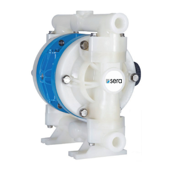
Summary of Contents for Sera AP05
- Page 1 OPERATING INSTRUCTIONS AIR OPERATED DIAPHRAGM PUMP AP05 (plastic design) TRANSLATION OF THE ORIGINAL OPERATING INSTRUCTIONS...
- Page 2 AP05 (plastic) www.sera-web.com...
-
Page 3: Table Of Contents
AP05 (plastic) TABLE OF CONTENT IMPORTANT INFORMATION ����������������������������������������������������������������������������������������������������������������4 Export Information ........................ 4 Chemical Reaction Disclaimer ....................4 Unpacking & Inspection ......................4 SAFETY PRECAUTIONS ������������������������������������������������������������������������������������������������������������������������4 MATERIAL SPECIFICATION �������������������������������������������������������������������������������������������������������������������7 Material Profiles ........................7 DimensIons ........................... 8 Characteristic curves ......................8 Performance data ......................... -
Page 4: Important Information
U.S. Bureau of Industry and Security(BIS). This affects all sera airPUMP pumps constructed from PVDF with PTFE balls and diaphragms. Please Chemical Reaction Disclaimer The user must exercise primary responsibility in selecting the product’s materials of construction which are compatible with the... - Page 5 AP05 (plastic) WARNING Hot surfaces. sera airPUMPs are capable of handling liquids with temperatures as high as 104ºC (220ºF). This may cause the outer areas of the pump to become hot as well and could cause burns. WARNING If a diaphragm rupture occurs, material being pumped may be forced out of the air exhaust. Proper care should be taken, always wear protective clothing, eye protection &...
- Page 6 If pump is used with materials that tend to solidify or settle, the pump should be flushed after each use to prevent damage. CAUTION Use only genuine sera replacement parts to assure compatibility and longest service life. CAUTION Check the temperature limits for all wetted components when choosing pump materials. See table below.
-
Page 7: Material Specification
AP05 (plastic) MATERIAL SPECIFICATION MATERIAL PROFILES Operating temperature Material Chemical composition Description min� max� Thermoplastic that is resistant to alkali and 0°C 70°C Pure Polypropylene strong acids. (32°F) (158°F) Strong fluoropolymer with excellent chemical -12°C 104°C PVDF Pure Polyvinylidene Fluoride resistance. -
Page 8: Dimensions
AP05 (plastic) DIMENSIONS CHARACTERISTIC CURVES www.sera-web.com... -
Page 9: Performance Data
AP05 (plastic) PERFORMANCE DATA Air operated diaphragm pump AP05 (Plastic) Max Flow Rate: 77 Litre/min. (20 gal/m) Suction/Discharge Size: ½“ FBSP or FNPT Displacement Per Stroke: 0,08 Litre (0.020 gal) Air Inlet/Exhaust Size: ¼“ FNPT / ½“ FNPT Max Outlet Pressure:... -
Page 10: Installation / Start Up
Once the pump primes; the shut-off valve can be opened additionally to increase the pump’s flow. If the pump is oper-ating but not pumping any liquid see the troubleshooting section for tips & suggestions. Accessories Surge suppressors, spill stops & filter regulators are available and should be used with sera airPUMP. www.sera-web.com... -
Page 11: Troubleshooting Tips And Suggestions
AP05 (plastic) TROUBLESHOOTING TIPS AND SUGGESTIONS PUMP WILL NOT START OR CYCLEL: Blocked liquid pipe or hose - Clean out or replace ■ Clogged liquid chamber - Remove debris ■ Diaphragm shaft bushing / o-ring leak - Replace o-rings ■... -
Page 12: Maintenance
AP05 (plastic) MAINTENANCE Recommended tools for servicing pump Box wrench (10mm and 13mm) ■ Socket wrenches (20mm (2x)) ■ Snap ring pliers ■ Hex wrenches (3mm, 5mm and 6mm) ■ O-Ring pick ■ Torque wrench ■ Wet End Servicing (Installing Wet End Kit) Relieve airline pressure and fluid line pressures before conducting maintenance. - Page 13 AP05 (plastic) Repeat the above steps for the suction Remove both liquid chambers by remo- To remove the diaphragms (items manifold (item12). The seat o-rings, valve ving the (6) bolts (items 17) on each 20/ 21), begin by loosening the (2) seats and valve balls (items 13, 14, 15 liquid chamber using a 13mm (or ½“)
-
Page 14: Mounting
AP05 (plastic) MOUNTING Slide the center hole of one diaphragm (item 21) over the molded in bolt of an outer plate (item 19). The air side of the diaphragm is labeled and should face away from the plastic portion of the outer plate. - Page 15 AP05 (plastic) The other diaphragm(s) (items 20/21) and inner/ Tighten and torque the outer plates (item 19). If the outer plates (items 19 & 22) can be installed onto the pump is fitted with PTFE diaphragms (item 20), it is opposite end of the shaft (item 27).
-
Page 16: Air End Servicing (Installing Air End Kit)
AP05 (plastic) Place the larger valve seat o-rings (item 15) into the seat bores of the liquid chambers followed by the valve seats (item 14). Install the two smaller o-rings (item 13) into the face grooves in the valve seats. The seats are to be orientated so that the edge groove on the seat accepts the larger o-ring. -
Page 17: Shaft, Bushing And O-Ring Replacement
AP05 (plastic) SHAFT, BUSHING AND O-RING REPLACEMENT Remove the shaft bushing retaining ring (item 25) and Use the supplied grease packets to lightly grease the push the shaft bushing out of the center section. OD and ID o-rings (items 23 & 26) that come preinstal- led in the new shaft bushing supplied in air end kits. -
Page 18: Air Valve O-Ring Replacement
AP05 (plastic) AIR VALVE O-RING REPLACEMENT Plastic Air Valve Aluminum Air Valve To replace the valve cap o-ring remove the retaining To replace the valve cap o-rings (item 5), remove the ring (item 8), then unthread the valve cap (item 6) using (3) button head cap screws (item 7) using a 3mm hex a 6mm hex wrench. -
Page 19: Valve And Muffler Gasket Replacement
AP05 (plastic) VALVE AND MUFFLER GASKET REPLACEMENT Remove the valve body (item 3) by removing the four Pull the valve body and gasket (items 3 & 30) off the socket head cap screws (item 1) that attach the valve... -
Page 20: Replacement Air Valve Kit Installation
AP05 (plastic) REPLACEMENT AIR VALVE KIT INSTALLATION Remove the valve that is to be replaced by removing the (4) socket head cap screws with a 5mm hex wrench that ■ attaches the valve body to the muffler plate. Save the (4) cap screws, (4) lock washers, muffler plate, and muffler. All other valve components can be ■... - Page 21 AUFSTELLUNG / INSTALLATION airPUMP AP05 (plastic) Pos� Description Material Part-No� Qty� Buna-N 109418 109446 O-RING, 109447 VALVE SEAT LOWER Santoprene 109448 FEP-covered 109326 109291 VALVE SEAT PVDF 109296 Buna-N 109580 109583 O-RING, 109585 VALVE SEAT UPPER, Santoprene 109587 FEP-covered 109586...
- Page 22 PARTS SUPPLIED IN PLASTIC VALVE AIR END KIT 109672 PARTS SUPPLIED IN ALUMINUM VALVE AIR END KIT 109594 PARTS SUPPLIED IN PLASTIC REPLACEMENT VALVE KIT 109675 PARTS SUPPLIED IN ALUMINUM REPLACEMENT VALVE KIT 109588 AP05 with air valve PP-GFK AP05 with air valve Aluminium Pos� Description Part-No� Qty�...
- Page 23 AP05 (plastic) Maximum Torque Settings AP05 (Plastic designs) Asterisk (*) from the exploded view diagram indicates fasteners to be torqued. Stainless steel to stainless steel fasteners should be lubricated to prevent galling. A Plus sign (+) on the above torque values indicates a lubricated fastener.
-
Page 24: Clearence Certificate
Machines which are operated with radioactive media shall only be inspected and/or repaired in the safety area of the owner by a sera specialized fitter. The clearance certificate is part of the inspection-/repair order. sera reserves the right to refuse acceptance of the order for other reasons. DOWNLOAD Clearance Certificate... -
Page 25: Ec Declaration Of Conformity
EC DECLARATION OF CONFORMITY Original Business name and full address of the manufacturer: sera GmbH, sera-Straße 1, D - 34376 Immenhausen Name and address of the person authorised to compile the technical file: Sabine Morell, sera-Straße 1, D – 34376 Immenhausen Description and identification of the machinery: Air-operated diaphragm pump for dosing fluids for industrial applications. - Page 26 AP05 (plastic) NOTES www.sera-web.com...
- Page 27 AP05 (plastic) NOTES www.sera-web.com...
- Page 28 FOLLOW US sera GmbH sera-Str. 1 34376 Immenhausen Germany Tel. +49 5673 999 00 Fax +49 5673 999 01 info@sera-web.com www.sera-web.com...
Need help?
Do you have a question about the AP05 and is the answer not in the manual?
Questions and answers