Table of Contents
Advertisement
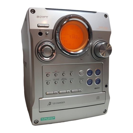
SERVICE MANUAL
Ver 1.0 2001. 03
• CHC-CL1/CL3 are composed of following models.
As for the service manual, it is issued for each component model,
then, please refer to them.
COMPONENT MODEL NAME
COMPACT DISC DECK
RECEIVER SYSTEM
FRONT SPEAKER
SS-SCL1 (SILVER)
SYSTEM
SS-SCL1B (BLACK)
SPECIFICATIONS
General
Power requirements
U.S.A. model:
120 V AC, 60 Hz
AEP models:
230 V AC, 50/60 Hz
Australian and New Zealand models:
230 – 240 V AC, 50/
60 Hz
Mexican model:
120 V AC, 60 Hz
Korean model:
220 V AC, 60 Hz
Other models:
120 V, 220 V, 230 –
240 V AC, 50/60 Hz
Adjustable with voltage
selector
Power consumption
U.S.A. model:
CHC-CL1:
100 watts
AEP models:
CHC-CL3:
165 watts
CHC-CL1:
100 watts
CHC-CL3/CL1:
0.5 watts (at the Power
Saving Mode)
Other models:
CHC-CL3:
165 watts
CHC-CL1:
100 watts
Dimensions (w/h/d) incl. projecting parts and controls
Amplifier/Tuner/Tape/CD section:
Approx. 215 × 285 ×
421 mm
Approx. 210 × 285 ×
Speaker:
260 mm
Mass
Amplifier/Tuner/Tape/CD section:
CHC-CL3:
Approx. 8.0 kg
CHC-CL1:
Approx. 7.7 kg
Speakers:
Approx. 3.8 kg net per
speaker
Supplied accessories
Remote (1)
R6 (size AA) batteries (2)
AM loop antenna (1)
FM lead antenna (1)
Speaker pads (8)
Design and specifications are subject to change
without notice.
Sony Corporation
9-873-859-11
2001C1600-1
Audio Entertainment Group
© 2001.3
General Engineering Dept.
CHC-CL1/CL3
CHC-CL3
CHC-CL1
HCD-CL3
HCD-CL1
SS-SCL3
COMPACT Hi-Fi COMPONENT SYSTEM
• Abbreviation
MX : Mexican model
AUS : Australian model
KR : Korea model
TW : Taiwan model
PARTS LIST
Part No.
Description
ACCESSORIES & PACKING MATERIALS
********************************
1-476-443-11 COMMANDER, STANDARD (RM-SCL1)
1-501-374-11 ANTENNA, LOOP (AM)
1-501-659-41 ANTENNA (FM) (CL1:US,AUS,E,MX,TW,KR/CL3:MX,KR)
1-501-804-11 ANTENNA (FM) (CL1:AEP,UK/CL3:AEP,UK)
4-210-254-01 CUSHION (FOOT)
4-228-952-01 COVER,BATTERY (FOR RM-SCL1)
4-233-430-11 MANUAL, INSTRUCTION
(CL1:US,AEP,UK,AUS,E,TW/CL3:AEP,UK) (ENGLISH)
4-233-430-21 MANUAL, INSTRUCTION (CL1:AEP/CL3:AEP) (FRENCH)
4-233-430-31 MANUAL, INSTRUCTION (CL1:AEP,E,MX/CL3:AEP,MX)
4-233-430-41 MANUAL, INSTRUCTION (CL1:AEP/CL3:AEP)
4-233-430-51 MANUAL, INSTRUCTION (CL1:AEP/CL3:AEP)
4-233-430-61 MANUAL, INSTRUCTION (CL1:AEP/CL3:AEP) (PORTUGUESE)
4-233-430-71 MANUAL, INSTRUCTION (CL1:AEP/CL3:AEP)
4-233-430-81 MANUAL, INSTRUCTION (CL1:AEP/CL3:AEP) (RUSSIAN)
4-233-430-91 MANUAL, INSTRUCTION (CL1:TW) (CHINESE)
4-233-431-11 MANUAL, INSTRUCTION (CL1:KR/CL3:KR) (KOREAN)
US Model
Australian Model
CHC-CL1
AEP Model
UK Model
E Model
CHC-CL1/CL3
Remark
(SPANISH)
(GERMAN, DUTCH, ITALIAN)
(SWEDISH, POLISH)
(DANISH, FINNISH)
Advertisement
Table of Contents


Need help?
Do you have a question about the SS-SCL3 and is the answer not in the manual?
Questions and answers