Table of Contents
Advertisement
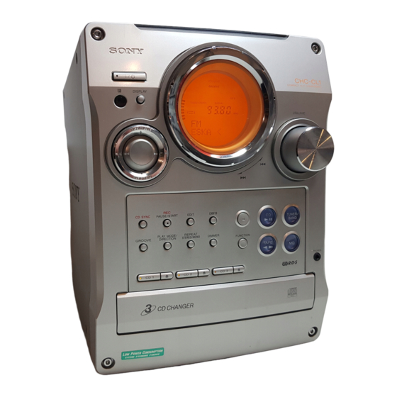
SERVICE MANUAL
Ver 1.0 2001. 03
• CHC-CL1/CL3 are composed of following models.
As for the service manual, it is issued for each component model,
then, please refer to them.
COMPONENT MODEL NAME
COMPACT DISC DECK
RECEIVER SYSTEM
FRONT SPEAKER
SS-SCL1 (SILVER)
SYSTEM
SS-SCL1B (BLACK)
SPECIFICATIONS
General
Power requirements
U.S.A. model:
120 V AC, 60 Hz
AEP models:
230 V AC, 50/60 Hz
Australian and New Zealand models:
230 – 240 V AC, 50/
60 Hz
Mexican model:
120 V AC, 60 Hz
Korean model:
220 V AC, 60 Hz
Other models:
120 V, 220 V, 230 –
240 V AC, 50/60 Hz
Adjustable with voltage
selector
Power consumption
U.S.A. model:
CHC-CL1:
100 watts
AEP models:
CHC-CL3:
165 watts
CHC-CL1:
100 watts
CHC-CL3/CL1:
0.5 watts (at the Power
Saving Mode)
Other models:
CHC-CL3:
165 watts
CHC-CL1:
100 watts
Dimensions (w/h/d) incl. projecting parts and controls
Amplifier/Tuner/Tape/CD section:
Approx. 215 × 285 ×
421 mm
Approx. 210 × 285 ×
Speaker:
260 mm
Mass
Amplifier/Tuner/Tape/CD section:
CHC-CL3:
Approx. 8.0 kg
CHC-CL1:
Approx. 7.7 kg
Speakers:
Approx. 3.8 kg net per
speaker
Supplied accessories
Remote (1)
R6 (size AA) batteries (2)
AM loop antenna (1)
FM lead antenna (1)
Speaker pads (8)
Design and specifications are subject to change
without notice.
Sony Corporation
9-873-859-11
2001C1600-1
Audio Entertainment Group
© 2001.3
General Engineering Dept.
CHC-CL1/CL3
CHC-CL3
CHC-CL1
HCD-CL3
HCD-CL1
SS-SCL3
COMPACT Hi-Fi COMPONENT SYSTEM
• Abbreviation
MX : Mexican model
AUS : Australian model
KR : Korea model
TW : Taiwan model
PARTS LIST
Part No.
Description
ACCESSORIES & PACKING MATERIALS
********************************
1-476-443-11 COMMANDER, STANDARD (RM-SCL1)
1-501-374-11 ANTENNA, LOOP (AM)
1-501-659-41 ANTENNA (FM) (CL1:US,AUS,E,MX,TW,KR/CL3:MX,KR)
1-501-804-11 ANTENNA (FM) (CL1:AEP,UK/CL3:AEP,UK)
4-210-254-01 CUSHION (FOOT)
4-228-952-01 COVER,BATTERY (FOR RM-SCL1)
4-233-430-11 MANUAL, INSTRUCTION
(CL1:US,AEP,UK,AUS,E,TW/CL3:AEP,UK) (ENGLISH)
4-233-430-21 MANUAL, INSTRUCTION (CL1:AEP/CL3:AEP) (FRENCH)
4-233-430-31 MANUAL, INSTRUCTION (CL1:AEP,E,MX/CL3:AEP,MX)
4-233-430-41 MANUAL, INSTRUCTION (CL1:AEP/CL3:AEP)
4-233-430-51 MANUAL, INSTRUCTION (CL1:AEP/CL3:AEP)
4-233-430-61 MANUAL, INSTRUCTION (CL1:AEP/CL3:AEP) (PORTUGUESE)
4-233-430-71 MANUAL, INSTRUCTION (CL1:AEP/CL3:AEP)
4-233-430-81 MANUAL, INSTRUCTION (CL1:AEP/CL3:AEP) (RUSSIAN)
4-233-430-91 MANUAL, INSTRUCTION (CL1:TW) (CHINESE)
4-233-431-11 MANUAL, INSTRUCTION (CL1:KR/CL3:KR) (KOREAN)
US Model
Australian Model
CHC-CL1
AEP Model
UK Model
E Model
CHC-CL1/CL3
Remark
(SPANISH)
(GERMAN, DUTCH, ITALIAN)
(SWEDISH, POLISH)
(DANISH, FINNISH)
Advertisement
Table of Contents

Related Manuals for Sony SS-SCL1


Summarization of Contents
SPECIFICATIONS
General
Provides general electrical and physical characteristics of the system.
PARTS LIST
Accessories and Packing Materials
Lists included accessories and packaging components.
REVISION HISTORY
Revision Log
Records changes made to the service manual over time.
SAFETY CHECK-OUT
AC Leakage Testing
Details AC leakage testing methods and limits for safety.
SECTION 1 SERVICING NOTES
Optical Pick-up and Laser Handling
Precautions for handling the laser pick-up block and diode.
SECTION 2 GENERAL
Button Descriptions
Explains the function of various buttons on the unit and remote.
SYSTEM SETTINGS
Setting the System Clock
Step-by-step guide to set the internal clock time.
SECTION 3 DISASSEMBLY
Top Panel and Side Panel Removal
Details on removing the top and side panels of the unit.
DISASSEMBLY SUB-SECTIONS
Cassette Mechanism Disassembly
Steps to disassemble the cassette mechanism.
CD Mechanism Disassembly
Steps for removing the CD mechanism.
SECTION 4 TEST MODE
System Test Mode Overview
Overview of various test modes for system diagnostics.
SECTION 5 MECHANICAL ADJUSTMENTS
Torque Measurement Procedures
Procedures for measuring torque on various parts.
SECTION 6 ELECTRICAL ADJUSTMENTS
Head Azimuth Adjustment
Steps to adjust the record/playback head azimuth.
ELECTRICAL ADJUSTMENT PROCEDURES
Record Bias and Tape Speed Adjustment
Procedures for adjusting record bias and tape speed.
Record Level and CD Section Adjustments
Procedures for record level and CD section adjustments.
E-F Balance Check
Procedure for checking and adjusting E-F balance.
SECTION 7 DIAGRAMS
Circuit Boards Location
Identifies the physical location of various circuit boards.
SECTIONAL DIAGRAMS
Block Diagrams - CD Section
Provides block diagrams for the CD section.
MAIN SECTION SCHEMATICS
Main Section Circuit Diagrams
Circuit schematic for the main section of the unit.
BD (CD) SECTION DIAGRAMS
BD (CD) Board Schematic and PWB
Schematic and PWB layout for the BD (CD) board.
DRIVER SECTION DIAGRAMS
Driver Section Schematic and PWB
Schematic and PWB layout for the driver section.
TC SECTION DIAGRAMS
TC Section Schematic and PWB
Schematic and PWB layout for the TC section.
AMP SECTION DIAGRAMS
AMP Section Schematic and PWB
Schematic and PWB layout for the AMP section.
PANEL SECTION DIAGRAMS
Panel Section Schematic and PWB
Schematic and PWB layout for the panel section.
TRANS SECTION DIAGRAMS
Trans Section Schematic and PWB
Schematic and PWB layout for the transformer section.
POWER SECTION DIAGRAMS
Power Section Schematic and PWB
Schematic and PWB layout for the power supply section.
IC PIN FUNCTION DESCRIPTION
IC401 Main Section Pin Functions
Details pin functions for the main control IC.
IC BLOCK DIAGRAMS
IC101 CD Board Block Diagram
Block diagram for the CD IC101.
EXPLODED VIEWS
Side Panel and Back Panel Exploded View
Exploded view showing parts for the side and back panels.
EXPLODED VIEWS SUB-SECTIONS
Front Panel Exploded View
Exploded view illustrating the front panel components.
Chassis Section Exploded View
Exploded view of the chassis and its associated parts.
CD Mechanism Deck Exploded View
Exploded view of the CD mechanism deck.
ELECTRICAL PARTS LIST
Capacitors and Resistors List
Lists capacitors and resistors with their specifications.
ELECTRICAL PARTS LIST SUB-SECTIONS
Transistors and Diodes List
Lists transistors and diodes used in the unit with specifications.
Switches and Miscellaneous Parts
Lists switches, fuses, and connectors with specifications.
SPEAKER SYSTEM SPECIFICATIONS
Speaker System Details
Details for the speaker system component.
Need help?
Do you have a question about the SS-SCL1 and is the answer not in the manual?
Questions and answers