Table of Contents
Advertisement
Quick Links
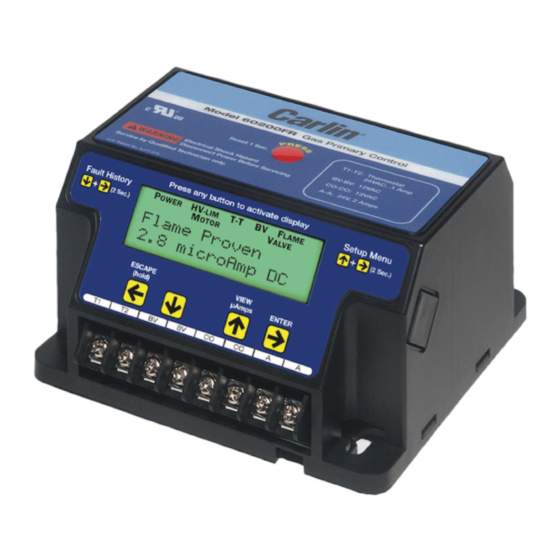
• On-Board LCD Screen
• Fully Programmable Settings
• 32 Cycle Fault History
• Alarm Contacts
• Serviceman Reset Protection
• Blocked Vent Protection
• Provides Flame Signal in Microamps
• Low Voltage Terminals
It is important that the installation of the oil burner,
piping and fittings, safety devices, controls, electrical
wiring and equipment be done in accordance with
national and/or local regulations of the authorities
having jurisdiction over such installation.
©
Copyright 2020 — Carlin Combustion Technology
Model 60200FR
Gas Burner
Primary Control
Installation and
Operating Instructions
For Use By Qualified Service Technicians Only
Power input
(red/white wire) ................................ 120 VAC, 60 HZ, 9 VA
Limit circuit input
(black wire) .............................................. 120 VAC, 60 HZ
Motor load
(orange wire) .........10 FLA / 60 LRA (reduce by valve load)
Ignitor load
(blue wire) .................................... 120 VAC, 60 HZ, 500 VA
Valve load
(violet wire) .......................................... 120 VAC, 60 HZ, 2A
Auxiliary ..................................................... 120 VAC, 1 amp
Operating voltage ................................120 VAC - 132 VAC
Alarm contacts (dry contacts)....................24V, AC/DC, 2A
Operating temperature limits ..................+32°F to +140°F
Thermostat ..................................................... 24 VAC, 0.1A
Blocked Vent ................................................. 12 VDC, 2mA
CO .................................................................. 12 VDC, 2mA
Agencies .............................. UL recognized (US & Canada)
FROZEN PIPES/WATER DAMAGE
This is not a freeze protection device. Suitable freeze protection
monitoring or other precautions are recommended to protect
against ruptured pipes/water damage caused by fuel outage,
safety related fault conditions or equipment failure.
C a r l i n C o m b u s t i o n T e c h n o l o g y
126 Bailey Rd
Ph 203-680-9401
Tech Support 800-989-2275
North Haven, CT 06473
Fx 203-680-9403
carlincombustion.com
Advertisement
Table of Contents

Related Manuals for Carlin 60200FR


Summary of Contents for Carlin 60200FR
- Page 1 C a r l i n C o m b u s t i o n T e c h n o l o g y 126 Bailey Rd North Haven, CT 06473 Ph 203-680-9401 Fx 203-680-9403 © Copyright 2020 — Carlin Combustion Technology Tech Support 800-989-2275 carlincombustion.com...
- Page 2 Installing The 60200FR control must be installed and serviced only by a qualified service technician. Always disconnect power source before wiring to avoid electrical shock or damage to the control. All wiring must comply with applicable codes and ordinances.
- Page 3 Lockout on flame failure. Step 1 Remove the 60200FR control from the electrical junc- tion box to access the terminal strip located on the bottom of Step 3 Connect 120 VAC Neutral to the white wire attached the control.
- Page 4 Wiring must comply with local and national electrical codes, and with the wiring diagram. Commercial Gas Train 120V FACTORY WIRING FIELD WIRING SEE PAGE 3 EZGas Pro FACTORY WIRING FIELD WIRING SEE PAGE 3 EZGas 120V FACTORY WIRING FIELD WIRING SEE PAGE 3 Carlin Combustion Technology...
- Page 5 30 seconds of inactivity or by a call for heat. Pre-Purge 30 Seconds Pressing the button again will leave the setting as is and move to the next option – Trial for Ign 4 Seconds Carlin Combustion Technology...
- Page 6 X X Sec X X Sec Standby 5 9 Sec During Pre-Ignition, the ignitor turns on and enters Trial for No Call for Heat Ignition. Trial for Ign X X Sec SEE STATUS ICONS – PAGE 8 Carlin Combustion Technology...
- Page 7 Total/Run History Press the button again to determine how many cycles ago In addition to the Fault History (left),the 60200FR also logs the the fault occurred. total run history of the control. To enter this menu, simultane- ously press the buttons for 3 seconds.
- Page 8 Flashes in unison with other status icons indicating a problem exists in that area Status Icons will appear at the top of the 60200FR display to MOTOR Indicates that the motor is energized (flashes if mo- indicate the control’s current operating condition.
Need help?
Do you have a question about the 60200FR and is the answer not in the manual?
Questions and answers