Advertisement
Quick Links
Patent No. 10,529,191
• Universal Replacement – for Carlin,
Beckett, Honeywell and ICM Controls
• Includes patented Smart Ignition
feature
• On-Board LCD Screen – no special
tool needed
• Optimized for performance with all
fuel blends, including B100
• Fully Programmable Settings
• 32 Cycle Fault History
• Alarm Contacts
• Communications Port
• Serviceman Reset Protection
• Blocked Vent Protection
• Built-in Pump Prime
• Recessed Spade Connectors
• Provides CAD Cell Reading in OHMS
It is important that the installation of the oil burner,
piping and fittings, safety devices, controls, electrical
wiring and equipment be done in accordance with
national and/or local regulations of the authorities
having jurisdiction over such installation.
©
Copyright 2023 — Carlin Combustion Technology
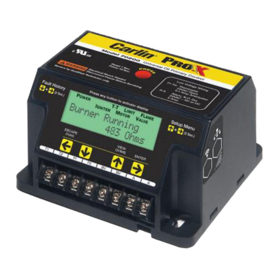
Model 70200
Universal Oil
Primary Control
Installation and
Operating Instructions
For Use By Qualified Service Technicians Only
Power input
(red/white wire) ................................ 120 VAC, 60 HZ, 9 VA
Limit circuit input
(black wire) .............................................. 120 VAC, 60 HZ
Motor load
(orange wire) .........10 FLA / 60 LRA (reduce by valve load)
Ignitor load
(blue wire) .................................... 120 VAC, 60 HZ, 500 VA
Valve load
(violet wire) .......................................... 120 VAC, 60 HZ, 2A
Vent load ................................................................. 0.1 amp
Line heater ................................................................ 1 amp
Alarm contacts (dry contacts)....................24V, AC/DC, 2A
Operating temperature limits ..................+32°F to +140°F
Storage temperature limits ...................... -40°F to +185°F
Thermostat anticipator current .......................... 0.1 A, AC
Agencies .............................. UL recognized (US & Canada)
C a r l i n C o m b u s t i o n T e c h n o l o g y
126 Bailey Rd
Ph 203-680-9401
Tech Support 800-989-2275
North Haven, CT 06473
Fx 203-680-9403
carlincombustion.com
Advertisement

Related Manuals for Carlin 70200


Summary of Contents for Carlin 70200
- Page 1 Primary Control Installation and Operating Instructions For Use By Qualified Service Technicians Only Patent No. 10,529,191 • Universal Replacement – for Carlin, Power input (red/white wire) ........ 120 VAC, 60 HZ, 9 VA Beckett, Honeywell and ICM Controls Limit circuit input •...
-
Page 2: Hazard Definitions
FROZEN PIPES/WATER DAMAGE This is not a freeze protection device. Suitable freeze protection monitoring or other precautions are recommended to protect against ruptured pipes/water damage caused by fuel outage, safety related fault conditions or equipment failure. Carlin Combustion Technology MN70200B 101323... - Page 3 Installing and Wiring The 70200 control must be installed and serviced only by a qualified service technician. Do not connect an external voltage to the thermostat terminals T1 and T2. This will damage the control and may result in a dangerous operating condition Always disconnect power source before wiring to avoid electrical shock or damage to the control.
- Page 4 (or lockout) to enter setup. To enter the Settings Mode: Press the buttons simultaneously for 2 seconds. The display will show – Settings Press To Exit Hold Carlin Combustion Technology MN70200B 101323...
- Page 5 Stabilization period, the control will recycle (60 - 65 seconds). Following this recycle, the control will operate in Intermittent NOTE: If the Pro-X 70200 is being connected to both a com- Duty mode (ignition on throughout the call for heat) for 5 heat bustion air proving switch and blocked vent switch, call Carlin cycles.
- Page 6 10 seconds. The display will read Pump Prime. Status Icons Status Icons will appear at the top of the 70200 display to indicate the control’s current operating condition. POWER Indicates that the control is powered (flashes if voltage is too low or too high) Displayed when the TT terminals are physically jumpered, jumpered in the set-up menu, or when thermostat is calling for heat.
- Page 7 Continue pressing the button to examine the following information recorded during the fault cycle. The 70200 stores information from the last 32 cycles in which • Line Voltage a fault condition occurred. To Enter the Fault History , simul- taneously press and hold the buttons for 2 seconds.
- Page 8 • CAD cell defective. not reset it from a latch-up condition. • Oil valve (if used) stuck in closed position. • Check wiring connections. • Maxed out Smart Ignition cycles – check combustion ohms, vacuum (oil supply), draft MN70200B 101323 Carlin Combustion Technology...
-
Page 9: Message Guide
• Oil line/supply issue • High vacuum or draft Flame @ Preignit • Unexpected flame during pre-ignition • Stuck valve • RF interference/AC line noise • Are tabs properly aligned with electrodes Continued on next page MN70200B 101323 Carlin Combustion Technology... - Page 10 • Oil line/supply issue • High vacuum or draft No Flame; High Lockout due to no flame + motor current not dropping • Check Motor Motor Current below 50% from it’s peak startup reading • Check Pump MN70200B 101323 Carlin Combustion Technology...
- Page 11 NOTES Carlin Combustion Technology MN70200B 101323...
- Page 12 NOTES Carlin Combustion Technology 126 Bailey Road North Haven, CT 06473 Phone 203-680-9401 Fax 203-764-1714 info@carlincombustion.com www.carlincombustion.com e-mail us at: visit our website: MN70200B - B100 101323 © Copyright 2023— Carlin Combustion Technology...
Need help?
Do you have a question about the 70200 and is the answer not in the manual?
Questions and answers