Table of Contents
Advertisement
Quick Links
Advertisement
Table of Contents

Related Manuals for Newland NLS-EM3080 V2


Summary of Contents for Newland NLS-EM3080 V2
- Page 1 NLS-EM3080 V2 OEM Scan Engine Integration Guide...
- Page 2 All pictures in this manual are for reference only and actual product may differ. Regarding to the product modification and update, Fujian Newland Auto-ID Tech. Co., Ltd. reserves the right to make changes to any software or hardware to improve reliability, function, or design at any time without notice.
-
Page 3: Revision History
Revision History Version Description Date V1.0.0 Initial release. November 21, 2018... -
Page 5: Table Of Contents
Table of Contents Revision History ..................................- 3 - About This Guide..................................1 Introduction ..................................1 Chapter Description ................................1 Explanation of Symbols ..............................1 Related Documents ................................2 Chapter 1 Getting Started ................................3 Introduction ..................................3 Illumination & Aimer ................................3 Chapter 2 Installation ................................... - Page 6 Power Supply ................................. 13 Ripple Noise ................................... 13 DC Characteristics ................................. 13 Operating Voltage / Current ........................... 13 I/O Voltage ................................13 Timing Sequence ................................14 Power Up and Power Down Timing Sequence ...................... 14 Chapter 4 Interfaces ................................... 15 Interface Pinouts ................................
-
Page 7: About This Guide
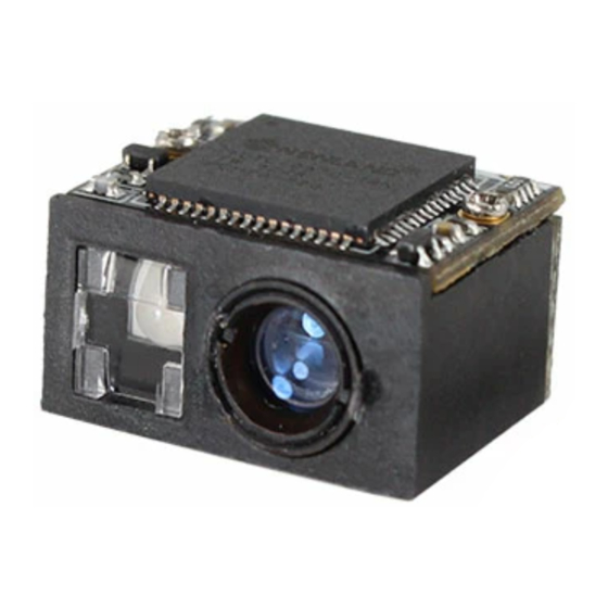
About This Guide Introduction The NLS-EM3080 V2 OEM scan engines (hereinafter referred to as “the EM3080 V2” or “the engine”) are armed with CMOS image capturer and the Newland patented , a computerized image recognition system-on-chip, featuring fast scanning and accurate decoding on barcodes on virtually any medium-paper, magnetic card, mobile phones and LCD displays. -
Page 8: Related Documents
Related Documents • 12-pin FFC connector specification, Xiamen Mos Electronic Technology Co., Ltd, Model:0.5-23-12PBX-P, http://www.fjmos.com/. -
Page 9: Chapter 1 Getting Started
Chapter 1 Getting Started Introduction The EM3080 V2 is an area image engine for barcode reading. LED Compliance Statement The EM3080 V2 complies with IEC 62471:2006 for LED safety. The EM3080 V2 contains: • a CMOS image sensor and its lens •... - Page 10 user to position the target barcode within the engine’s field of view. The illumination can be programmed On or Off. The EM3080 V2 uses the red LED for illumination, so the engine shows better reading performance on barcodes printed in non-red colors.
-
Page 11: Chapter 2 Installation
Chapter 2 Installation Introduction This chapter explains how to install the EM3080 V2, including general requirements, housing design, and physical and optical information. △ Caution: Do not touch the imaging lens when installing the engine. Be careful not to leave fingerprints on the lens. !... -
Page 12: Thermal Considerations
Thermal Considerations Electronic components in the EM3080 V2 will generate heat during the course of their operation. Operating the EM3080 V2 in continuous mode for an extended period may cause temperatures to rise on CPU, CIS, LEDs, DC/DC, etc. Overheating can degrade image quality and affect scanning performance. -
Page 13: Front View
Front View Figure 2-2 Bottom View Figure 2-3 Side View Figure 2-4... -
Page 14: Housing Design
Housing Design ※ Note: Conduct an optical analysis for the housing design to ensure optimal scanning and imaging performance. Housing design should make sure that internal reflections from the aiming and illumination system are not directed back to the engine. The reflections from the housing or window can cause problems. For particular window tilt angles, the unwanted reflections can bounce off the top or bottom and reach the engine. -
Page 15: Window Material And Color
Table 2-2 Distance from the front of the engine housing (b) Minimum Angle (Tilted Window) 10mm 15mm 20mm Uncoated, minimum window positive tilt (+w) 30° 28° 26° 25° Uncoated, minimum window negative tilt (-w) Anti-reflection coated, single side, minimum window positive tilt (+w) 26°... -
Page 16: Coatings And Scratch Resistance
Pay extra attention to the wavefront distortion when using plastic materials. Plastic materials are not recommended for tilted windows; colored windows are not recommended if the engine is used to scan barcodes on moving objects. Coatings and Scratch Resistance Scratch on the window can greatly reduce the performance of the EM3080 V2. It is suggested to use abrasion resistant window material or coating. -
Page 17: Window Size
Window Size The window must not block the field of view and should be sized to accommodate the aiming and illumination envelopes shown below. Horizontal: Figure 2-6 Vertical: Figure 2-7... -
Page 18: Roll, Skew And Pitch
Three different reading angles, roll, skew and pitch are illustrated in Figure 2-8. Roll refers to rotation around the Z axis, skew to rotation around the X axis and pitch to rotation around the Y axis. For the engine’s technical specifications, please visit the Newland website or contact your dealer. Figure 2-8 Ambient Light The EM3080 V2 shows better performance with ambient light. -
Page 19: Chapter 3 Electrical Specifications
Chapter 3 Electrical Specifications Power Supply Do not power up the EM3080 V2 until it is properly connected. Be sure the power is cut off before connecting a cable to or disconnecting a cable from the host interface connector. Hot-plugging could damage the engine. Unstable power supply or sharp voltage drops or unreasonably short interval between power-ons may lead to unstable performance of the engine. -
Page 20: Timing Sequence
Timing Sequence Power Up and Power Down Timing Sequence Figure 3-1 1. In the diagram above, it takes A+B (about 3200ms) for the engine to power up: A is reset time (about 200ms), B is time needed to start the engine. The engine is ready to receive commands via its serial/USB port after the power-up sequence completes. -
Page 21: Chapter 4 Interfaces
Chapter 4 Interfaces Interface Pinouts The physical interface of the EM3080 V2 consists of 12-pin FFC connector: • 12-pin FFC connector can be used as TTL-232 interface or USB interface. The figure below illustrates the positions of 12-pin FFC connector on the EM3080 V2’s decoder board, as well as the pin layout of the FFC connector. -
Page 22: 12-Pin Ffc Connector
12-pin FFC Connector The following table lists the pin functions of the 12-pin FFC connector. Table 4-1 PIN# Signal Function Remark Unconnected 3.3V power supply Power-supply ground TTL level 232 receive data TTL level 232 transmit data USB_D+ USB D+ differential data signal USB_D- USB D- differential data signal Unconnected... -
Page 23: Connector/Cable Specifications (Unit: Mm)
Connector/Cable Specifications (Unit: mm) The EM3080 V2 is equipped with a 12-pin FFC connector. 12-pin FFC Connector The 12-pin FFC connector on the EM3080 V2 is a Xiamen Mos Electronic Technology Co., LTD FFC connector (Model No.: 0.5-23-12PBX-P). Figure 4-2 12-pin FFC Cable A 12-pin cable can be used to connect the engine’s 12-pin FFC connector to a host device. -
Page 24: External Circuit Design
External Circuit Design Beeper Circuit The circuit below is used to drive an external beeper. The nBUZZ signal is from PIN 9 of the 12-pin FFC connector. BAT760 AS903Q R6 10 BUZZ 2N3904 Figure 4-4 Trigger Circuit The circuit below is used to provide the engine with a signal to trigger a scan and decode session. The TRIG signal is from PIN 12 of the 12-pin FFC connector. -
Page 25: Chapter 5 Auxiliary Tools
Chapter 5 Auxiliary Tools The EM3080 V2 provides the following tool to assist users in engine performance evaluation, application development and engine configuration. The EVK is provided to help users to test and evaluate the EM3080 V2, which contains beeper & beeper driver circuit, trigger &... - Page 26 Newland Auto-ID Tech. Co., Ltd. (Headquarters) 3F, Building A, No.1, Rujiang West Rd., Mawei, Fuzhou, Fujian, China 350015 Tel: +86 - (0) 591-83978605 Fax: +86 - (0) 591-83979216 E-mail: contact@nlscan.com Web: www.newlandaidc.com Newland Europe BV Rolweg 25, 4104 AV Culemborg, The Netherlands...
Need help?
Do you have a question about the NLS-EM3080 V2 and is the answer not in the manual?
Questions and answers