Table of Contents
Advertisement
Quick Links
Advertisement
Table of Contents

Related Manuals for Newland NLS-EM20


Summary of Contents for Newland NLS-EM20
- Page 1 NLS-EM20 OEM Scan Engine Integration Guide...
- Page 2 All pictures in this manual are for reference only and actual product may differ. Regarding to the product modification and update, Fujian Newland Auto-ID Tech. Co., Ltd. reserves the right to make changes to any software or hardware to improve reliability, function, or design at any time without notice. The information contained herein is subject to change without prior notice.
- Page 3 Revision History Version Description Date V1.0.0 Initial release. July 24, 2015 1. Deleted the “Ambient Environment” section in Chapter 2. 2. Modified the “Operating Voltage” and “Operating Current” V1.0.1 November 20, 2016 sections in Chapter 3.
-
Page 4: Table Of Contents
Table of Contents Chapter 1 Introduction ............................1 Overview ............................... 1 Illumination ..............................1 Aimer ................................1 Chapter 2 Installation ............................2 General Requirements ..........................2 ESD ................................ 2 Dust and Dirt ............................2 Thermal Considerations......................... 2 Installation Orientation ........................... 3 Optics ................................ - Page 5 Chapter 4 Interfaces ............................11 Connections & Pinouts ..........................11 TTL-232 ............................... 12 USB ..............................13 Micro USB ............................13 Host Interface Connectors .......................... 14 12-Pin FPC Connector ......................... 14 Micro USB Connector .......................... 15 Communication Interfaces .......................... 16 External Circuits ............................17 Good Read LED Circuit ........................
-
Page 7: Chapter 1 Introduction
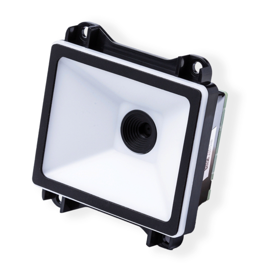
Chapter 1 Introduction Overview The EM20 OEM scan engine, armed with the Newland patented , a computerized image recognition system, brings about a new era of 2D barcode scan engines. The EM20’s 2D barcode decoder chip ingeniously blends technology and advanced chip design &... -
Page 8: Chapter 2 Installation
Chapter 2 Installation General Requirements ESD protection has been taken into account when designing the EM20 and the engine is shipped in ESD safe packaging. Always exercise care when handling the engine outside its package. Be sure grounding wrist straps and properly grounded work areas are used. Dust and Dirt The EM20 must be sufficiently enclosed to prevent dust particles from gathering on the lens and circuit board. -
Page 9: Installation Orientation
Installation Orientation There is a threaded mounting hole at each of the EM20’s four corners for fastening the engine to a mounting surface with machine screws. The following figure illustrates a front view of the EM20 after correct installation. -
Page 10: Optics
Optics Window Placement The window should be positioned properly to let the illumination and aiming beams pass through as much as possible and no reflections back into the engine (reflections can degrade the reading performance). The window should be mounted close to the front of the engine (parallel) and the window should be as thin as possible. -
Page 11: Window Size
Window Size The window must not block the field of view. Horizontal: FOV Envelope Vertical: FOV Envelope... -
Page 12: Ambient Light
Ambient Light The EM2096 shows better performance with ambient light and it is well able to handle the flicker in fluorescent lights using 50-60Hz AC power. However, high-frequency pulsed light can result in performance degradation. Eye Safety The EM20 has no lasers. It uses white LEDs to create illumination beam. The LEDs are bright, but testing has been done to demonstrate that the engine is safe for its intended application under normal usage conditions. -
Page 13: Mounting
Mounting The illustrations below show the mechanical mounting dimensions for the EM20. The structural design should leave some space between components. Front View (unit: mm) Side View (unit: mm) -
Page 14: Top View (Unit: Mm)
Top View (unit: mm) -
Page 15: Chapter 3 Electrical Specifications
Chapter 3 Electrical Specifications Power Supply Do not power up the EM20 until it is properly connected. Be sure the power is cut off before connecting a flexible cable to or disconnecting a flexible cable from the host interface connector. Hot-plugging could damage the engine. -
Page 16: Dc Characteristics
DC Characteristics Operating Voltage Ta=23℃ Parameter Description Minimum Typical Maximum Unit Voltage Drain Drain High Level Input Voltage -0.5 Low Level Input Voltage High Level Output Voltage -0.3 Low Level Output Voltage Operating Current Ta=23℃,V Operating Current Standby Current Sleep Current 198mA (typical) 16mA 10mA... -
Page 17: Chapter 4 Interfaces
Chapter 4 Interfaces Connections & Pinouts The EM20 is equipped with a 12-pin FPC connector and a Micro USB connector. The 12-pin FPC connector can be used as TTL-232 interface or USB interface. The Micro USB connector can only be used as standard USB interface. Fig. -
Page 18: Ttl-232
TTL-232 The table below describes the pin functions of FPC connector used as TTL-232 interface. PIN# Signal Name Function 232INV Output: High = TTL-232 interface; Low = USB interface Power: supply voltage input Ground: power and signal ground Input: TTL level 232 receive data Output: TTL level 232 transmit data nCTS Input: TTL level 232 clear to send... -
Page 19: Usb
The table below describes the pin functions of FPC connector used as USB interface. PIN# Signal Name Function Output: High=TTL-232 interface; Low=USB 232INV interface Power: supply voltage input Ground: power and signal ground Input/Output: USB D- signal Reserved Reserved Input/Output: USB D+ signal Reserved Reserved Output: Active high, scan engine is in sleep... -
Page 20: Host Interface Connectors
Host Interface Connectors The EM20 is equipped with a 12-pin FPC connector and a Micro USB connector. 12-Pin FPC Connector The EM20 uses an FFC/FPC connector (CF20121V0R0-LF) manufactured by CviLux. Fig. 4-2... -
Page 21: Micro Usb Connector
Micro USB Connector The EM20’s Micro USB connector is a standard connector and can be used accordingly. Fig. 4-3... -
Page 22: Communication Interfaces
Communication Interfaces The EM20 can communicate with the host device via its TTL-232 interface. This interface is applicable to most system architectures. For those requiring RS-232, a TTL-232 to RS-232 conversion circuit is needed. The EM20’s TTL-232 interface supports baud rates from 1200bps to 115200bps; it does not support hardware flow control. -
Page 23: External Circuits
External Circuits Good Read LED Circuit The circuit below is used to drive an external LED for indicating good read. The left part shows internal Good Read LED driver circuit on the decoder board and the right part shows external circuit that users may utilize in actual application. -
Page 24: Sleep Mode Led Circuit
Sleep Mode LED Circuit The circuit below is used to drive an external LED for indicating that the engine is in sleep mode. The left part shows internal Sleep Mode LED driver circuit on the decoder board and the right part shows external circuit that users may utilize in actual application. -
Page 25: Wake-Up Circuit
Wake-Up Circuit The circuit below is used to wake the engine from sleep mode. The right part shows internal driver circuit on the decoder board and the left part shows external circuit that users may utilize in actual application. The nWAKE signal is from Pin 11 of the 12-pin FPC connector. Users can adjust the external circuit and its function as per actual needs, on condition that the external circuit matches the internal circuit. -
Page 26: Chapter 5 Development Tools
Chapter 5 Development Tools The EM20’s development tools include both software and hardware and can be utilized for engine performance evaluation, application development and engine configuration. The EVK is provided to help users to test and evaluate the EM20, which contains beeper & beeper driver circuit, LED &... - Page 27 Headquarters Fujian Newland Auto-ID Tech. Co., Ltd. 3F, Building A, No.1, Rujiang West Rd., Mawei, Fuzhou, Fujian, China 350015 TEL: +86 - (0) 591-83978605 FAX: +86 - (0) 591-83979216 E-mail: marketing@nlscan.com WEB:www.nlscan.com Newland Europe BV Rolweg 25, 4104 AV Culemborg, The Netherlands...
Need help?
Do you have a question about the NLS-EM20 and is the answer not in the manual?
Questions and answers