Table of Contents
Advertisement
Quick Links
Advertisement
Table of Contents

Related Manuals for Steadicam Volt


Summary of Contents for Steadicam Volt
- Page 1 Steadicam Volt User Guide ® ™ LIT-817001, Rev B...
-
Page 2: Table Of Contents
Balance Power on Operating Settings Volt Installation Types of installations Installation of Volt complete kit Installation of Volt onto bare gimbals Flip Button Motor belts Gimbal upgrades Archer/Archer2 gimbal upgrade Archer/Archer2 gimbal balancing Ultra2, Shadow, Clipper gimbal upgrade PRO CineLive, PRO CineHD gimbal upgrade... - Page 3 The Tiffen Company 90 Oser Avenue Hauppauge, NY 11788 Visit us at Tiffen.com...
-
Page 4: Introduction
Working with the sled’s inertia and neutral balance, the Volt generates an “artificial bottom-heaviness” to keep the horizon level and headroom stable. With Volt, the operator can concentrate on precise framing, timing, navigating, and other more interesting aspects of operating. -
Page 5: Components
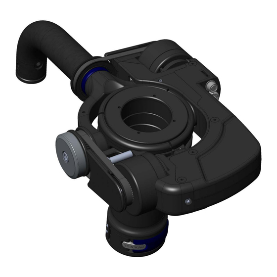
Components Steadicam Volt shown on M-2 gimbal ® ™ ™ Handle pulley Pan encoder ring inside Handle motor and belt Trunnion pulley Main power/control input & encoder jack Trunnion motor Trunnion screw access and belt Pan encoder Gimbal clamp lever... - Page 6 Components Steadicam Volt™ Control Box ® Main power switch Nose box rods Level trim button MDR-3 mount Roll strength dial Run/pause switch Damping adjuster Power and Mode LEDs Tilt strength dial Power input jack from sled Display jack Main power/control output to...
- Page 7 Hook lock lever The new dock The padded dock is designed to protect the Volt electronics as well as make docking and balancing easier. The low-profile design ensures nothing contacts the Volt gimbal motor assembly when docked, and the “over-center” arm swings into place to secure the sled. Docking on the gimbal also reduces shock loads on your gimbal bearings.
- Page 8 Components Included with Steadicam Volt™ M-series gimbal kit ® • M-2 gimbal with Volt Motor Assembly, internal encoder, pulleys and belts installed and tested • Volt Control Box (mustache box) • Gimbal cable, short (817-0135) • M-2 gimbal post spacers for 1.5”, 1.58” and 1.75” posts •...
- Page 9 MACHINED FILLETS: .003R -.005R PROPERTY OF THE TIFFEN MACHINE FINISH 63 RMS 817-7955 COMPANY. ANY REPRODUCTION ITEM NO. PART NUMBER DESCRIPTION QTY. IN PART OR AS A WHOLE FILE NAME: INTERPRET DRAWING PER: WITHOUT THE WRITTEN ANSI Y14.5 2009 817-7912 MTG PLATE, VOLT...
-
Page 10: Let's Get Started
“flip” button once to reorient the Volt sensors. See page 43 to learn about the flip button. If the Volt was installed at your dealer, the flip procedure will have been performed already. -
Page 11: Choosing Sides
Notes about left or right side motors The Volt gimbal motor assembly, casually referred to as the hockey stick, may be mounted to either side of the gimbal yoke. In general, regular operators prefer to mount it to the left and goofy operators mount it to the right. -
Page 12: Balance
TIP: Build your rig with more pan inertia (monitor and batteries extended) to increase stability in the pan axis, which the Volt motors do not affect. This will reduce unwanted panning motions in your image. Balance the sled with a normal to long drop time. - Page 13 Balance Make sure the sled does not pan when holding a tilt. If so, a tiny adjustment to your side-side balance should correct this. Otherwise, go back and re-check your dynamic balance. When changing accessories above the gimbal, like lenses or filters, re-balance on the dock with a normal drop time and then go fully neutral again.
-
Page 14: Power On
NOTE: Any sled with internal Volt controls, such as an M-2, will always align the gimbal handle with the REAR of the post, no matter which side of the top stage the built-in knobs are installed. - Page 15 The blue LEDs glow. You’ll do this EVERY TIME you power on the Volt. IF the control box is mounted for goofy operators (knobs on the LEFT) align the gimbal handle with the FRONT of the post and simultaneously power on the Volt.
- Page 16 You should now feel the horizon assistance and artificial bottom-heaviness of normal mode. The Volt only needs to have the post encoder aligned when powering on. Pausing and activating the Volt can be toggled with the handle in any orientation.
-
Page 18: Operating
Here are some tips on how to optimize the Volt, starting with trimming the post angle and the two operating modes. We’ll adjust the control box dials later. - Page 19 Using your sled’s integrated tilt head maintains the vertical post, ideal for panning. First, pause the system, change the tilt and re- balance the sled. Then run the Volt and set a new tilt trim by short pressing the gimbal button.
- Page 20 Operating Should you wish to set the ROLL trim, SHORT- press the trim button on the control box and position the sled to the new level position while the LEDs blink for 5 seconds. When LED blinking stops, your new horizon position (or Dutch angle) is now stored in memory.
- Page 21 Operating The included padded dock is essential to protect the Volt’s motors and electronics. Other methods of docking may damage the unit. Always use the over-center hook while docked. TIP: You can remove unnecessary docking rings from your post and gain precious gimbal height! The dock offers the ability to tilt the gimbal up to 30˚...
-
Page 22: Settings
Settings Control box settings The three dials on the control box allow you to customize the behavior of the Volt in two axes, roll and tilt, independently. Additionally, the damping dial controls how the system returns the sled to vertical. - Page 23 Settings The ROLL dial controls the strength of the motors in the roll axis. This equates to how strongly the rig seeks a level horizon side-to-side. To help retain subtlety of control, start with low assist levels and add strength as needed for each shot.
- Page 24 Settings Recommended settings Try these settings for the different situations listed. These recipes are just a starting point; experiment, starting with reduced strength and find exactly what works best for you, for each shot. TYPICAL MODE Every day operating, easy tilt. ROCK AND ROLL Free to tilt or roll Dutch angles.
- Page 25 It’s similar to the drag setting on a fluid head. Use as little TILT as necessary to match the inertial resistance of your pan axis for the smoothest diagonals. • Share settings with other Volt operators as we all explore the future of Steadicam operating! ®...
-
Page 28: Types Of Installations
Volt™ yourself ® Most operators add Volt to their rigs by ordering the complete M-2 gimbal with the Volt motor assembly already installed on their preferred side, ready to go. We’ll cover the steps involved with complete gimbal installs first, followed by the full install of Volt components onto all compatible gimbals later. - Page 30 Mounting the Volt control box onto an integrated rod system, like on an M-1 or M-2, is easy. If you’re using rod adapters or MDR plates on other rigs, make sure the control box is affixed rigidly to the sled.
- Page 31 12V IN port. NOTE: If you use an aftermarket power cable, confirm the polarity is correct. Volt is protected against reverse voltage, but won’t work very well without power.
-
Page 32: Installation Of Volt Complete Kit
The M-2 gimbal has been designed to accommodate posts of 1.5 in, 1.58 in and 1.75 in diameter by incorporating snap-in inserts. The complete Volt kit includes a balanced M-2 gimbal with Volt motor assembly installed on your chosen side, ready to be installed. - Page 33 Installation Next, add the lower post insert. There is a locating pin inside the gimbal which must be indexed with the hole in the insert. For 1.5” and 1.58” posts, the shorter flange is oriented UP, so the insert is flush with the bottom of the gimbal when installed.
- Page 34 Installation When necessary, the over-center lock on the gimbal is adjusted with the clamp lever CLOSED. Use a 3/32” Allen wrench to turn each screw an equal, tiny amount. You don’t want to over-tighten these, so take your time. Test the action of the clamp lever, and the holding power of the clamp.
- Page 35 NOTE: For preassembled Volt gimbals, you do NOT need to press the flip button. This procedure was done at the factory. Your Volt equipped sled should be ready for action! Now go back to page 9, and get ready to balance before powering on.
-
Page 38: Installation Of Volt Onto Bare Gimbals
Volt in roughly an hour. Unlike other “horizon” gadgets, you’ll probably never want to take it off. The initial steps for adding Volt to ALL gimbals require you to pull the gimbal from your post, so take particular care if this is the first time you’ve disassembled the com- ponents of your system. - Page 39 Installation Take a moment with your blue whale wrench to make sure the gimbal top cap is tight and everything spins smoothly. Use alcohol to clean the top cap when you’re done. NOTE: The pan encoder ring will cover the wrench holes.
- Page 40 Installation Slide the gimbal handle pulley over the gimbal handle. Line up the lock screws with the four holes on the knurled blue ring. Use a 0.05” Allen key to tighten the four lock screws enough to secure the pulley. Do not over-tighten.
- Page 41 For M-2 and upgraded gimbals, install one thread adapter ONLY on the side of the gimbal where you will mount the motor assembly. Right side shown here. If mounting Volt on the left, thread the adapter to that side. Leave the trunnion screws in place.
- Page 42 Installation Install the trunnion pulley in place of the M-1 trunnion screw, with the washer behind it. Use the narrow pins on your blue whale wrench to tighten. NOTE: The pulley should be installed as shown, with the relief around the lock screw hole facing outwards.
- Page 43 Installation Affix the pan encoder horseshoe to the top of the gimbal, using a 3/32” Allen wrench to turn the included 3/8” long 8-32 button head screws (part SCI-B012B1230.) Screw location may differ from illustration. NOTE: The M-2 pan encoder slots into the front of the gimbal, see the M-2 manual.
- Page 44 Volt housing before mounting. Hold the gimbal handle up slightly to enable proper clearance while installing the Volt. Align the relief on the inside of the Volt and fit it against the gimbal. Using the 1/8” Allen key inserted through the hole in the side of the housing, tighten the trunnion screw into the threaded cap adapter.
- Page 45 Installation Snug the opposing pair of set screws on Volt motor assembly with a 1/16” Allen key. There’s one above and one below the yoke. Tighten them each a little until they both contact the yoke. Do not over-tighten these!
-
Page 46: Flip Button
If you mounted Volt on the LEFT side of the gimbal, skip this step and proceed to the next section. Also, if Volt arrived mounted on the right of the gimbal from the factory, this step has already been performed. - Page 47 Power off the unit, and the new setting is stored. Only press it once! Each consecutive 6-second press will toggle LEFT/RIGHT side operation. Replace the plastic cover. NOTE: If you flip your Volt to LEFT side mounting in the future, you’ll have to repeat the invert button process.
-
Page 48: Motor Belts
Motor belts Adding the belts The two belts transfer power from the Volt motors to the gimbal yoke and gimbal handle. The belts will never stretch and should not need replacement with normal use. Installing them will take finding the right belt angle and rotation of the pulleys, but they are self-aligning once in place. - Page 49 7/64” Allen key. Slowly adjust each belt tension, a little at a time, so the Volt is loaded evenly. To test belt tension, grasp each belt halfway between the motor and pulley with a firm pinch, and twist the belt 45 degrees.
- Page 50 NOTE: You may wish to adjust the tension again with Volt powered on to check its behavior. The finishing touch is to spin the trunnion weight into the 1/4-20” threads of the trunnion pulley.
- Page 51 TIP: Depending on your normal builds, you may prefer the optional “long” gimbal cable. Your Volt equipped sled should be ready for action! Now go back to page 9, and get ready to balance before powering on.
-
Page 54: Gimbal Upgrades
Archer/Archer2 Gimbal upgrade It’s recommended you have an experienced Steadicam technician do the service for you, but upgrading an Archer or Archer2 gimbal is a fairly straightforward procedure. Here are the assembly notes used by the factory for reference. Visit tiffen.com/steadicam/voltsystem/... - Page 55 9. Install 305-7123 onto 305-7122 using 5x SCI-4008F1230 screws and Loctite 222. Note orientation of ring with respect to 305-7122. 10. If gimbal is not being outfitted with a volt system at this time, install 3x SCI-B014C1210 into the threaded holes in 305-7122. Omit if a volt system is to be installed.
-
Page 56: Archer/Archer2 Gimbal Balancing
10. Repeat drop test again. If unit does not repeat check to make sure all clamps, plates, camera and whatever else might shift or become loose is stable and not shifting the balance point. 11. Re-install bearing cap covers, if not installing Volt. - Page 57 13170 (REF) 305-7123 FLANGE, GIMBAL 305-7124 FLANGE, GIMBAL, ORG-134878 305-7126 PIVOT SHAFT, GIMBAL 305-7127 WASHER, GIMBAL SCI-B012B1230 305-7158 YOKE, VOLT 315-7137 HANDLE, QUICK RELEASE 315-7138 HANDLE,GIMBAL 800-7635 BRAKE,.055" WALL,.560" TK 804-7109 SCREW, GIMBAL PIVOT 315-7138 815-7111 CAP, YOKE, GIMBAL MSC-104218...
- Page 58 Ultra2, Shadow, Clipper Gimbal upgrade It’s recommended you have an experienced Steadicam technician do the service for you, but upgrading an Ultra2 or Shadow gimbal is a fairly straightforward procedure.. Here are the assembly notes used by the factory for your reference. Visit tiffen.com/steadicam/voltsystem/...
- Page 59 9. Balance gimbal as required using balance procedure. Note that pin- 137003 is used to install and remove 800-7179-xx parts. 10. Complete assembly by installing 2x 815-7111 caps. Omit if a volt system is to be installed. NOTE: Perform the gimbal balancing procedure found on...
- Page 60 Ultra2, Shadow, Clipper " 0 " 0 " 6 Ø Ø " 0 " 5 " 7 ® " 1 " 1 " 5 " 5 . I . I B I...
- Page 62 PRO CineLive, PRO CineHD Gimbal upgrade It’s recommended you have an experienced Steadicam technician do the service for you, but upgrading a PRO gimbal is a fairly straightforward procedure. Here are the assembly notes used by the factory for your reference. Visit tiffen.com/steadicam/voltsystem/...
- Page 63 Image of the correct axle is shown on page 59 for comparison. 6. If volt is to be installed at this point, first install 305-7175 pulley (not shown) onto the PRO gimbal handle before installing the handle onto the yoke.
- Page 64 PRO CineLive, PRO CineHD " 0 " 0 " 6 " 0 " 5 " 7 ® " 1 " 1 " 5 " 5 . I . I B I...
-
Page 66: U2, Shadow, Clipper, Pro Gimbal Balancing
U2, Shadow, Clipper, PRO gimbal balancing BALANCE PROCEDURE 1. Mount simulated camera weight (maximum payload capacity of sled recommended) onto sled and place onto appropriate balance spud. 2. Fine tune fore-aft and left-right balance by adjusting fore/aft and side/side adjustment knobs on stage. - Page 67 U2, Shadow, Clipper, PRO gimbal balancing c) NOTE that the 800-7179-xx and 815-7110-xx spacers come in three different sizes (.000”, +.001” and -.001”) as indicated by the grooves cut into the parts (Refer to image below). The type of spacer used will depend on the gimbal that is being balanced.
- Page 68 U2, Shadow, Clipper, PRO gimbal balancing 10. Note the type of spacer installed 11. If the gimbal housing bearing needs to be shifted to the left as noted in step 5a, this means that the spacer on the left side of yoke will need to be decreased (i.e. go from .000 to -.001) and the spacer on the right will need to be increased (i.e.
- Page 69 You can now fly with the upgraded yoke OR install the Steadicam ™ Volt starting on page 35. ®...
-
Page 70: Troubleshooting Checklist
Did you remember to align the gimbal handle while powering on? Control box knobs on the right, align with the rear of the post; knobs on the left, align with the front of the post. Internal Volt brain? Align the gimbal handle with the rear of the post regardless of which side the knobs are mounted. -
Page 71: Frequently Asked Questions
Why does my VOLT not correct the horizon when I shoot at a Dutch angle? Answer: The VOLT is designed to control the roll axis of the sled up to a ±25° roll angle, with reduced power being applied to the Roll motor beyond ±5°. - Page 72 Answer: Center balancing of the gimbal is a very precise procedure that requires calibration of the gimbal to within the thickness of a human hair or less. A gimbal with a VOLT fitted is difficult to center balance to this level of precision, nor is it necessary. The good news is that with the VOLT turned on and operating, a slightly out of balance or slightly un-dynamically balanced sled will have little to no effect on the operation.
- Page 73 The encoder ring’s orientation is not important. NOTE: Check to see that the VOLT pan encoder is spaced the thickness of a folded piece of paper away from the magnetic encoder ring also after installation to avoid any potential gimbal friction.
- Page 74 Why is the rig panning when I tilt? Answer: Since the VOLT is only in control of the tilt and roll axis and not the pan axis, this axis is free to rotate. Any slight left-right imbalance or shift of balance when tilting of the sled will cause it to pan left or right.
- Page 75 Answer: The VOLT is designed to operate from 12Vdc to 17Vdc. Any voltage below 12V will start to affect the motor power of the VOLT and its ability to operate reliably. If the applied voltage to the VOLT drops too low, motor systems will be turned off. The LED’s on the motor drive will go off, but LED’s on Control Box may stay on.
-
Page 76: Electronics
Electronics 12V IN GIMBAL LEMO ECG.0B.303.CLL LEMO ECG.1B.308.CLL 1- PWR GND 1- PWR GND 2- 11-17Vdc 2- 11-17VDC 3- n/c 3- SIG GND 4- GP3 DISPLAY 5- SIG GND HIROSE HR10-7R-6S73 6- GP4 1- VCC 5V 7- SIG GND 2- LED DATA 8- GP5 3- LED CLK 4- GP6... -
Page 78: Contact Tiffen
There is no implied or expressed warranty regarding this material. Thanks for reading the fine print! STEADICAM®, M-1™, M-2™ and Steadicam® Volt™ are trademarks of the Tiffen Company, LLC. All other trademarks and product names appearing herein are the property of their respective owners.
Need help?
Do you have a question about the Volt and is the answer not in the manual?
Questions and answers