Table of Contents
Advertisement
Quick Links
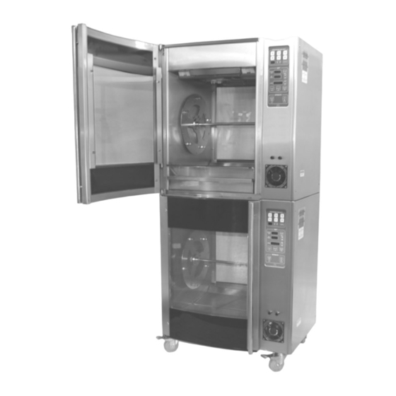
Models LCR5 and LCR7
5-Spit and 7-Spit Rotisserie Ovens
Installation, Service and Parts Manual
LBC Bakery Equipment, Inc.
6026 31
Ave NE
st
Tulalip, WA 98271, USA
Phone: 888-RACKOVN (888-722-5686)
Fax: 425-642-8310
Email:
parts@lbcbakery.com
Website:
www.lbcbakery.com
© 2017-2020
LBC BAKERY EQUIPMENT, INC. TULALIP, WA
PG 1
REV 12/2020
Advertisement
Table of Contents

Related Manuals for sinmag LBC LCR5


Summary of Contents for sinmag LBC LCR5
- Page 1 Models LCR5 and LCR7 5-Spit and 7-Spit Rotisserie Ovens Installation, Service and Parts Manual LBC Bakery Equipment, Inc. 6026 31 Ave NE Tulalip, WA 98271, USA Phone: 888-RACKOVN (888-722-5686) Fax: 425-642-8310 Email: parts@lbcbakery.com Website: www.lbcbakery.com © 2017-2020 LBC BAKERY EQUIPMENT, INC. TULALIP, WA PG 1 REV 12/2020...
-
Page 2: Read First
READ FIRST THIS MANUAL MUST BE RETAINED FOR FUTURE REFERENCE. READ, UNDERSTAND AND FOLLOW THE INSTRUCTIONS AND WARNINGS CONTAINED IN THIS MANUAL. DO NOT STORE OR USE GASOLINE OR OTHER FLAMMABLE VAPORS W A R N I N G AND LIQUIDS IN THE VICINITY OF THIS OR ANY OTHER APPLIANCE. -
Page 3: Table Of Contents
TABLE of CONTENTS Read First ..............2 Specifications . -
Page 4: Specifications
SPECIFICATIONS Actual Shipping Model Freight Class Weight Weight LCR5 32.5" 31.5" 21.7" 26.3" 27.1" 24.3" 450 lbs LCR7 38.4" 38.9" 26.5" 32.6" 32.6" 31.6" 610 lbs Min Circuit Ampacity Max Breaker Size Model Voltage 1 Phase 3 Phase 1 Phase 3 Phase LCR5 208 VAC... -
Page 5: Configurations
CONFIGURATIONS Countertop or Floor Mount Rotisserie Countertop: 4.0” Legs Floor: 6.0” Legs or 4.5” Swivel Casters with Brakes Stand Mount Rotisserie LST5 Stand (for LCR5 Rotisserie) or LST7 Stand (for LCR7 Rotisserie or LHC7 Holding Cabinet) Stacked Appliances Combinations: • 2 ea LCR5 Rotisseries 2 ea LCR7 Rotisseries •... -
Page 6: Conditions Of Installation
CONDITIONS of INSTALLATION LBC Bakery Equipment Co. shall, for a fee contingent on site location and provided that the conditions of installation are met, provide a factory-authorized service agency to install the LBC Rotisserie. The job site must be ready for the installation before LBC Bakery Equipment Co. -
Page 7: Receiving And Unpacking
RECEIVING and UNPACKING THIS APPLIANCE WEIGHS UP TO 610 LBS. FOR SAFE HANDLING, INSTALLER SHOULD OBTAIN HELP AS NEEDED OR EMPLOY APPROPRIATE MATERIAL- C A U T I O N HANDLING EQUIPMENT (SUCH AS A FORKLIFT, DOLLY OR PALLET JACK) TO REMOVE THE UNIT FROM ITS PACKING MATERIALS AND TO MOVE IT TO THE PLACE OF INSTALLATION. -
Page 8: Installation
INSTALLATION (Part 1 of 3) INSTALLATION OF THIS APPLIANCE MUST BE DONE BY PERSONNEL QUALIFIED TO WORK WITH ELECTRICITY. IMPROPER W A R N I N G INSTALLATION CAN CAUSE INJURY TO PERSONNEL AND/OR DAMAGE TO EQUIPMENT. ALL ELECRICAL, MECHANICAL CONNECTIONS AND C A U T I O N VENTILATION MUST MEET ALL FEDERAL, STATE AND LOCAL CODES OR ORDINANCES. - Page 9 INSTALLATION (Part 2 of 3) Drip Plates Unpack both drip plates (shipped inside the oven) and place at the bottom of the oven cook chamber. Electrical Power Connection A mounting plate with a 1.25” hole to connect an electrical conduit connector is installed at the bottom of the control compartment.
- Page 10 INSTALLATION (Part 3 of 3) Loading Door Switch Check While the oven is preheating, open the loading door and verify the following conditions: • The word “door” flashes in the timer display (NOTE: For ovens with two doors, each door must be checked independently) •...
-
Page 11: Controller Operation
CONTROLLER OPERATION PROGRAM SELECT Quick-Select Recipe Buttons Easy access to Recipe Arrow most-frequently-used Buttons & Display recipes Use arrow button to SAVE scroll through recipes Recipe Save Button (1 through 20); recipe After creating a recipe, number will appear in press this button twice display to save it... -
Page 12: Parts List
PARTS LIST (Part 1 of 5) BOTH HIGH AND LOW VOLTAGES ARE PRESENT INSIDE OF THIS APPLIANCE WHEN THE UNIT IS PLUGGED/WIRED INTO A LIVE W A R N I N G RECEPTACLE. BEFORE REPLACING ANY PARTS, DISCONNECT THE UNIT FROM THE ELECTRIC POWER SUPPLY. - Page 13 PARTS LIST (Part 2 of 5)
- Page 14 PARTS LIST (Part 3 of 5) Item No. Part Description Quantity Part No. Usage Controller 40102-76 15A Fuse 30900-01 Fuse Holder 30901-02 Axial Fan 71500-33 Fan Guard 50201-11 Handle, Loading Door 180-781-1 5-Spit only Handle, Loading Door 180-781-2 7-Spit only Loading Door, Inner 71300-32 5-Spit only...
- Page 15 PARTS LIST (Part 4 of 5) Item No. Part Description Quantity Part No. Usage Capacitor, Motor (4.0µF) 40704-10 Thermal Snap Disc (Relay Protection) 30301-05 Fan, Ceiling 71500-32 180-205-1 Fan Blade, Ceiling Door Switch Assembly 1 or 2 180-767-2 Thermal Snap Disc (Lights) 30301-06 7-Spit only Lamp Holder...
- Page 16 PARTS LIST (Part 5 of 5) ITEM PART DESCRIPTION QTY. NUMBER Motor 30200-51 (208VAC, 1ph, (Capless) 1600rpm) Lever, Motor 180-481 Brake Solenoid Fan Guard, 180-483 Motor Brake Solenoid Stop, Motor 180-484 Brake Solenoid Ring, Inner - 180-485 Teflon Washer, 70200-14 Friction Bracket, 180-480...
-
Page 17: Wiring Diagram
WIRING DIAGRAM (Part 1 of 2) - Page 18 WIRING DIAGRAM (Part 2 of...
Need help?
Do you have a question about the LBC LCR5 and is the answer not in the manual?
Questions and answers