Table of Contents
Advertisement
Quick Links
Browan Communications Inc.
No.15-1, Zhonghua Rd., Hsinchu Industrial Park,
Hukou, Hsinchu, Taiwan, 30352
Tel: +886-3-6006899
Fax: +886-3-5972970
Document Number
BQW_02_0016.004
WAPS-232N_LW
IOT Access Point
Outdoor Micro Gateway
Installation Guide
2020 © Browan Communications Inc., All Rights Reserved. This document is for planning purposes only and is not
intended to modify or supplement any specifications or warranties relating to products of Browan Communications.
Browan may make changes to specifications and descriptions at any time, without notice.
Advertisement
Table of Contents

Related Manuals for Browan WAPS-232N LW


Summary of Contents for Browan WAPS-232N LW
- Page 1 Outdoor Micro Gateway Installation Guide 2020 © Browan Communications Inc., All Rights Reserved. This document is for planning purposes only and is not intended to modify or supplement any specifications or warranties relating to products of Browan Communications. Browan may make changes to specifications and descriptions at any time, without notice.
-
Page 2: Revision History
Nov. 20, 2020 Modified ethernet waterproof connector assembly steps. Modified cover page, add model name for regulatory. .004 Apr. 1, 2022 Modification pictures and drawings on page 7. Updated the mount kit description on page12. © 2020 BROWAN COMMUNICATIONS INC. -
Page 3: Copyright
This document is copyrighted with all rights reserved. No part of this publication may be reproduced, transmitted, transcribed, stored in a retrieval system, or translated into any language in any form by any means without the written permission of BROWAN COMMUNICATIONS INC. Notice BROWAN COMMUNICATIONS INC. -
Page 4: Table Of Contents
2.2.2 Wall Mounting ........................15 2.2.3 Assembling and Securing the Waterproof Connector............20 2.3 Power ............................24 2.4 WAN ............................24 ..................25 HAPTER ATEWAY NSTALLATION EFERENCE 3.1 Wall-mount Installation ......................26 3.2 Base-mount Installation ......................32 © 2020 BROWAN COMMUNICATIONS INC. - Page 5 Figure 32 6 PVC cable protection hose ..................31 Figure 33 Actual View of a Base-mount Installation ..............32 Figure 34 Establishing the Base -1....................33 Figure 35 Establishing the Base -2....................33 Figure 36 Establishing the Base -3....................34 © 2020 BROWAN COMMUNICATIONS INC.
- Page 6 Table 2 List of Gateway Mounting Kit Components ..............12 Table 3 Description of Gateway Mounting Kit Components ............12 Table 4 List of Gateway Mounting Kit Components ..............15 Table 5 Connecting the RF Cable ....................19 © 2020 BROWAN COMMUNICATIONS INC.
-
Page 7: Chapter 1 Basic Equipment
3G/4G Antenna*1 ⚫ GPS Antenna*1 ⚫ Antenna Antenna ⚫ ⚫ Power RF Cable Ethernet Lightning Lightning Power Arrester Arrester 3G/4G Gateway Antenna 3G/4G Antenna Input:100-240V ~0.8A 50-60Hz Power Output:56V 0.536A Figure 1 System Architecture Diagram © 2020 BROWAN COMMUNICATIONS INC. -
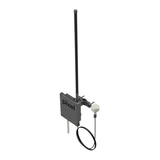
Page 8: Diagram Of Standard Product Equipment
RF CABLE (3000 mm) PE BAG DIPOLE ANT GPS ANTENNA POWER CORD MOUNT KIT ASS’Y POE ADAPTER EPE HOLDER RJ45 CONNECTOR CARTON (455*375*548 mm) Figure 2 Diagram of Standard Product Equipment Figure 3 Actual View of Standard Equipment © 2020 BROWAN COMMUNICATIONS INC. -
Page 9: Table 1 Device Specifications
⚫ Connector type: N-type Power code According to country standards ⚫ Power over Ethernet Power over Ethernet Output: (PoE) Pin Assignment and Polarity:4/5 (+), 7/8 (–) Output Power Voltage: 55Vdc User Port Power: 30Watts (Guaranteed) © 2020 BROWAN COMMUNICATIONS INC. - Page 10 Distance between the two antennas must be at least 100cm Lighting arrester ⚫ VSWR < 1.5 (Additional accessories) Note: Additional accessories are not included in the standard package. Please contact Browan personnel for additional purchases. © 2020 BROWAN COMMUNICATIONS INC.
-
Page 11: Chapter 2 Micro Outdoor Gateway System Installation Instructions
Chapter 2 Micro Outdoor Gateway System Installation Instructions 2.1 Exterior Appearance of the Gateway Device: Figure 4 Gateway Front and Rear View Figure 5 Gateway Installation Instructions © 2020 BROWAN COMMUNICATIONS INC. -
Page 12: Equipment Installation
Figure 6 Diagram of Equipment Installation Procedures 2.2.1 Post Mounting Pre-installation preparations Please make sure that all required tools and components are available prior to installation. ➢Tools: Allen wrenches (M5 and M8) or an adjustable wrench, Philips screwdriver © 2020 BROWAN COMMUNICATIONS INC. -
Page 13: Table 2 List Of Gateway Mounting Kit Components
Name of Component Outdoor Gateway Mounting Base Frame Adjustable Plate Fixing Plate Pack of Screws (includes the necessary types of screws) ➢Component details as described in the following: Table 3 Description of Gateway Mounting Kit Components © 2020 BROWAN COMMUNICATIONS INC. -
Page 14: Figure 7 Assembling The Base Frame - Diagram I
Step 1 Secure the base frame of the mount kit to the Gateway device, as shown in the figure below: Figure 7 Assembling the Base Frame - Diagram I © 2020 BROWAN COMMUNICATIONS INC. -
Page 15: Figure 8 Assembling The Base Frame - Diagram Ii
Install the base frame of the Gateway device against the pole by tightly fastening the fixing plate to the adjustable plate by using locking screws and adjustable screws. (It is recommended to install the Ethernet portal downwards.) Figure 9 Diagram I of Pole Installation © 2020 BROWAN COMMUNICATIONS INC. -
Page 16: Wall Mounting
➢List of components: Table 4 List of Gateway Mounting Kit Components CODE Name of Component Outdoor Gateway Mounting Base Frame Adjustable Plate Pack of Screws (includes the necessary types of screws) Expansion anchors (stainless steel) © 2020 BROWAN COMMUNICATIONS INC. -
Page 17: Figure 11 Width Between The Wall Mounting Holes
After drilling holes in the wall, insert and drive stainless steel anchors into the holes with a hammer until they are fully fixed inside the wall. Figure 12 Installation Diagram of Wall Mount Anchors (Stainless Steel) © 2020 BROWAN COMMUNICATIONS INC. -
Page 18: Figure 13 Installation Diagram Of Adjustable Plate
Secure the base frame of the mount kit to the Gateway with M5x8mm screws and connect the ground wire. The ground wire portal is situated at the corner of the Gateway with a icon. Figure 14 Assembling Diagram of Base Frame © 2020 BROWAN COMMUNICATIONS INC. -
Page 19: Figure 15 Depiction Of Ground Wire
Adjust the Gateway to the appropriate angle and fasten with M5x35mm adjustable screws to secure the device in place. Please see the following diagram: Figure 16 Installation Completion © 2020 BROWAN COMMUNICATIONS INC. -
Page 20: Figure 17 Connecting The Rf Cable
Lightning arrester ground Antenna connector wire ⚫Steps for installation: 1. Connect one end of the lightning arrester to the antenna connector. 2. Connect the type N connector of the RF cable to the lightning arrester. © 2020 BROWAN COMMUNICATIONS INC. -
Page 21: Assembling And Securing The Waterproof Connector
Please follow the steps below to assemble the waterproof connector. While installing, please ensure that the nut is securely fastened to prevent water or air from entering the gateway device. Side View © 2020 BROWAN COMMUNICATIONS INC. - Page 22 Process of Assembly: ① © 2020 BROWAN COMMUNICATIONS INC.
- Page 23 ② ③ © 2020 BROWAN COMMUNICATIONS INC.
-
Page 24: Figure 18 Steps For Installation
1. The device complies with the IP-67 waterproof standard. 2. After the installation is completed, we recommend the use of waterproof tape to seal the adjoining parts of the RJ-45 Ethernet connector and the antenna connector to enhance the level of waterproof protection. © 2020 BROWAN COMMUNICATIONS INC. -
Page 25: Power
PoE Out port (LAN) is to be connected to the Gateway Ethernet connector regardless of the transmission type. Note: The length of the network cable has to be less than 100m. Figure 20 Sim card installation © 2020 BROWAN COMMUNICATIONS INC. -
Page 26: Chapter 3 Gateway Installation Reference
5. Please ensure that there are no obstacles blocking the antenna and that the antenna is in a vertical state. 6. The way the gateway is installed should make it easy to maintain 7. The gateway, lightning surge arresters, and other relative equipment must be properly grounded. © 2020 BROWAN COMMUNICATIONS INC. -
Page 27: Wall-Mount Installation
Step 1. Please avoid walls that are connected to the water tower (an assessment made by a professional is required). Step 2. Use anchors to help secure the mount kit on the wall. Attach the Gateway device to the mount kit. Figure 22 Wall-mount Installation – Image 1 © 2020 BROWAN COMMUNICATIONS INC. -
Page 28: Figure 23 Wall-Mount Installation - Image 2
Step 3. The GPS and antenna are secured onto the wall by using a customized metal bracket. The antenna is secured onto the bracket by using the mounting kit or a customized U ring. Note: Use a level to make sure that the antenna is completely vertical. Figure 24 The Level © 2020 BROWAN COMMUNICATIONS INC. -
Page 29: Figure 25 Customized Metal Bracket - Image 1
Insert the GPS antenna into a 1-inch PVC pipe. Then, use two 1-inch U rings to secure the pipe to the rod. Figure 25 Customized Metal Bracket – Image 1 Figure 26 Customized Metal Bracket – Image 2 © 2020 BROWAN COMMUNICATIONS INC. -
Page 30: Figure 27 Customized Metal Bracket - Image 3
Figure 27 Customized Metal Bracket – Image 3 4.6mm 105mm 67mm Figure 28 Specifications for Customized Metal Bracket – Image 1 210mm 24mm 9∅ 61mm 46.5mm 61mm 67mm 16∅ 25mm 110mm Figure 29 Specifications for Customized Metal Bracket – Image 2 © 2020 BROWAN COMMUNICATIONS INC. -
Page 31: Figure 30 Lightning Protections And Grounding Equipment - Image 1
If grounding apparatus are not available, please fasten the ground wire to the mount kit to deliver a similar grounding effect. Figure 30 Lightning Protections and Grounding Equipment – Image 1 Figure 31 Lightning Protections and Grounding Equipment – Image 2 © 2020 BROWAN COMMUNICATIONS INC. -
Page 32: Figure 32 6 Pvc Cable Protection Hose
6 PVC cable protection hose. Network cables and RF cables should be secured to avoid wind-induced vibrations. Figure 32 6 PVC cable protection hose © 2020 BROWAN COMMUNICATIONS INC. -
Page 33: Base-Mount Installation
Make sure that there is sufficient thickness to support the base-mount. Step 3. Secure the base of the galvanized pipe. Please see image as shown below. © 2020 BROWAN COMMUNICATIONS INC. -
Page 34: Figure 34 Establishing The Base -1
Figure 34 Establishing the Base -1 1000mm 2000mm Figure 35 Establishing the Base -2 © 2020 BROWAN COMMUNICATIONS INC. -
Page 35: Figure 36 Establishing The Base -3
6 PVC cable protection hose. Network cables and RF cables should be secured to avoid wind-induced vibrations. Step 10. The grounding wire that connects the lightning arrester to the gateway device should be 5.5mm in diameter. © 2020 BROWAN COMMUNICATIONS INC.
Need help?
Do you have a question about the WAPS-232N LW and is the answer not in the manual?
Questions and answers