Table of Contents
Advertisement
Quick Links
Advertisement
Table of Contents

Related Manuals for Satel SATELLINE-M3-TR3


Summary of Contents for Satel SATELLINE-M3-TR3
- Page 1 SATELLINE-M3-TR3, -TR4 AND -R4 MODULE INTEGRATION GUIDE Version 3.4...
-
Page 2: Important Notice
Integration Guide, Version 3.4 IMPORTANT NOTICE All rights to this manual are owned solely by SATEL Oy (referred to in this user guide as SATEL). All rights reserved. The copying of this manual (without the written permission from the owner) -
Page 3: Restrictions On Use
Host product labeling requirements SATELLINE-M3-TR3 and –TR4 is intended to be integrated into a host device. Therefore the SATELLINE-M3-TR3 and –TR4 product related FCC ID and IC ID must be visible in the host device chassis: FCC ID: MRBSATEL-TA23... - Page 4 SATELLINE-M3-TR3, –TR4 and -R4 Integration Guide, Version 3.4 harmful interference to radio or television reception, which can be determined by turning the equipment off and on, the user is encouraged to try to correct the interference by one or more of the following measures: - Reorient or relocate the receiving antenna.
-
Page 5: Product Conformity
PRODUCT CONFORMITY Under the sole responsibility of manufacturer SATEL Oy declares that SATELLINE-M3-R4 receiver module and SATELLINE-M3-TR3 and –TR4 radio transceiver modules are in compliance with the essential requirements (radio performance, electromagnetic compatibility and electrical safety) and other relevant provisions of Directives 2014/53/EU and 2011/65/EU and Council recommendation 1999/519/EC Therefore the equipment is labeled with the following CE- marking. - Page 6 SATELLINE-M3-TR3, –TR4 and -R4 Integration Guide, Version 3.4...
-
Page 7: Warranty And Safety Instructions
-The radio transceiver module is only to be operated at frequencies allocated by local authorities, and without exceeding the given maximum allowed output power ratings. SATEL and its distributors are not responsible, if any products manufactured by it are used in unlawful ways. -
Page 8: Table Of Contents
SATELLINE-M3-TR3, –TR4 and -R4 Integration Guide, Version 3.4 TABLE OF CONTENTS IMPORTANT NOTICE ......................1 RESTRICTIONS ON USE ...................... 2 PRODUCT CONFORMITY ..................... 4 WARRANTY AND SAFETY INSTRUCTIONS ..............6 TABLE OF CONTENTS ......................7 INTRODUCTION ....................10 Terms and abbreviations ..................10 Description of the products................... - Page 9 SATELLINE-M3-TR3, –TR4 and -R4 Integration Guide, Version 3.4 CONFIGURATION ....................23 SATEL Configuration Manager software ............. 23 Changing parameters using SL commands ............24 6.2.1 SL Commands ..........................24 6.2.2 SL Command Mode ........................25 OPERATING MODES .................... 26 Safe mode ........................ 26 Power up / power down scenarios ...............
- Page 10 SATELLINE-M3-TR3, –TR4 and -R4 Integration Guide, Version 3.4 9.13 Channel list ......................36 Repeater –mode ...................... 37 9.14 9.15 Pacific Crest and TRIMTALK compatibility ............38 9.15.1 Settings in compatibility modes....................39 9.15.2 Repeater function ........................41 9.15.3 Support for Local / Remote addresses ..................41 9.15.4...
-
Page 11: Introduction
End users of SATEL products include both public organizations and private individuals. SATEL Oy is the leading European manufacturer of radio modems. SATEL radio modems have been certified in most European countries and also in many non-European countries. -
Page 12: Dte Connector
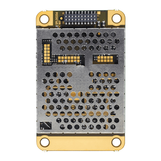
DTE port. The DTE interface is used to provide power to the module and communicate with the module. Available product variants can be viewed from SATEL WEB sites. 1.3 DTE connector The DTE connector is a 20-pin pass-through connector. This connector allows the pin to enter the connector from the bottom side and protrude thru the module PCB to the top side, allowing flexible mounting heights with various pin lengths. -
Page 13: Pin Order Of The Dte Connector
SATELLINE-M3-TR3, –TR4 and -R4 Integration Guide, Version 3.4 1.4 Pin order of the DTE connector Direction IN is data from DTE (Data Terminal Equipment) to the radio transceiver module. Direction OUT is data from the radio module to the DTE. - Page 14 SATELLINE-M3-TR3, –TR4 and -R4 Integration Guide, Version 3.4 GPIO5 CMOS Internal Pull Down Unconnected Internal Pull Up Input for service access. SERVICE Internally pulled high. Pull LOW / drive LOW to set UART1 (RD1, TD1) into known state. See separate section of manual.
-
Page 15: Mechanical Considerations
SATELLINE-M3-TR3, –TR4 and -R4 Integration Guide, Version 3.4 2 MECHANICAL CONSIDERATIONS 2.1 Fixing device to host The radio transceiver module can be mounted on to the host by using spacers and screws. Max. screw diameter is 3mm. 2.2 Host board instructions for mounting pegs In figure below is SATELLINE-M3-R4, -TR3 and TR4 with dimensions as millimeters. -
Page 16: Heat Transfer
SATELLINE-M3-TR3, –TR4 and -R4 Integration Guide, Version 3.4 2.3 Heat transfer While the module is operational especially when transmitter is operating, by the nature causes of electronic circuitry, there is extensive heat production which is suggested to keep on board as minimum as possible. -
Page 17: Technical Specifications
–TR4 and -R4 Integration Guide, Version 3.4 3 TECHNICAL SPECIFICATIONS Receiver part specifications applies to SATELLINE-M3-R4 receiver module. SATELLINE-M3-TR3 and –TR4 complies with the following international standards: EN 300 113-2 EN 301 489-1, -5 EN 60950-1 FCC CFR47 PART 90... - Page 18 16FSK FEC ON (TR4): 28800 bps (25 kHz) 14400 bps (12.5 kHz) Air Interface Encryption AES128 Programmable Data Format Asynchronous data 4FSK, GMSK (SATELLINE-M3-TR3) Modulation 4-, 8-, 16FSK, GMSK (SATELLINE-M3-TR4) GENERAL DC ≤ f ≤ 1 kHz Operating voltage +4.0 VDC min.
-
Page 19: Absolute Maximum Ratings
SATELLINE-M3-TR3, –TR4 and -R4 Test condition �� = 4.0 V and �� Integration Guide, Version 3.4 ���� �� = 25 °C According to EN 300 113-1 V.1.7.1 measurement setup The measured average of a sample of 19 M3-TR3 modules Higher values exceed the -36 dBm spurious limit at the antenna e.g. EN 300 113-1 requirement. -
Page 20: Default Delivery Values
SL Command Mode ON/OFF Repeater Mode ON/OFF 0 …. 65535 ms TX Delay Over-the-Air-Encryption ON/OFF Use Channel List ON/OFF Power Save Mode ON/OFF Add RSSI to Data ON/OFF Priority Tx/Rx Radio state Tx/Rx Tx/Rx, Rx Note*) Ask availability from SATEL... -
Page 21: Time Parameters For Startup And Shutdown Sequences
SATELLINE-M3-TR3, –TR4 and -R4 Integration Guide, Version 3.4 5 TIME PARAMETERS FOR STARTUP AND SHUTDOWN SEQUENCES Parameter Recom. Time Explanation Input >50µs When voltage is applied to VCC_IN the capacitor filter capacitors inside the module are charge time charged, creating a small current surge. If... -
Page 22: Startup Sequence
SATELLINE-M3-TR3, –TR4 and -R4 Integration Guide, Version 3.4 5.1 Startup sequence The following diagram will describe the startup sequence. Figure 7. Startup sequence. 5.2 Shutdown sequence The following diagram will describe the shutdown sequence. Figure 8. Shutdown sequence. -
Page 23: Stat Pin
SATELLINE-M3-TR3, –TR4 and -R4 Integration Guide, Version 3.4 5.3 Stat pin The STAT pin indicates the status of the device. It can be used to drive a LED using a series resistor. STAT pin drive capability is 10mA (loads the VCC_IO). -
Page 24: Configuration
6.1 SATEL Configuration Manager software SATEL Configuration Manager is a PC software for the configuration of SATELLINE-M3-R/TR, SATEL-R/TR –module based radio models, covering most of the SATEL radio products. Minimum requirements: SATEL Configuration Manager PC-program COM port with baud rate min. -
Page 25: Changing Parameters Using Sl Commands
CR/LF characters are added to end the response messages (unless they are already present) in order to make parsing easier. Settings can be toggled, SL Commands ON/OFF, CR/LF ON/OFF. See Appendix 12 for SL commands. In order to get information of the latest and/or special SL commands please contact SATEL. -
Page 26: Command Mode
The SL commands can be disabled or enabled by using SL commands or toggling the “SL Command mode” parameter via the SATEL Configuration Manager, version v1.3.15 or newer. By default the SL Command mode is set to ON. If the SL Command mode is set to OFF then the SL commands can be enabled or disabled by using the below described procedure. -
Page 27: Operating Modes
Stat Pin in 250ms interval indicating an Error and reboots the device after 5s. Transmitting/Receiving is prohibited during malfunction. When connecting to the device with SATEL Configuration Manager the Error code is shown in pop up box. If the device does not recover after multiple reboots, please contact SATEL Oy. -
Page 28: Sleep Mode
SATELLINE-M3-TR3, –TR4 and -R4 Integration Guide, Version 3.4 In the “OFF” state current consumption is only that of leakage current from an LDO (0.34 mA). In this state all non-essential parts off the module are powered down and all settings / state information that are not stored in NVM are reset. -
Page 29: Restart
SATELLINE-M3-TR3, –TR4 and -R4 Integration Guide, Version 3.4 The length of the whole sleeping period (t ) is calculated by decreasing the shortest time sleep between transmitted packets (t ) with safety margin (t ) and transmission time of the... -
Page 30: Serial Interface
SATELLINE-M3-TR3, –TR4 and -R4 Integration Guide, Version 3.4 8 SERIAL INTERFACE The radio modem is referred to as DCE (Data Communication Equipment) whereas the device connected to it, typically a PLC or a PC, is referred to as DTE (Data Terminal Equipment). -
Page 31: Data Buffering
SATELLINE-M3-TR3, –TR4 and -R4 Integration Guide, Version 3.4 8.2 Data buffering Whenever the radio modem is in Data Transfer Mode it monitors both the radio channel and the serial interface. When the terminal device starts data transmission the radio modem switches to transmission mode. -
Page 32: Rf Interface
The setting and/or using of non-approved power levels may lead to prosecution. SATEL and its distributors are not responsible for any illegal use of its radio equipment, and are not responsible in any way of any claims or penalties arising from the operation of its radio equipment in ways contradictory to local regulations and/or requirements and/or laws. -
Page 33: Receiver
FEC (error correction). Air rate bps @ Sensitivity (BER 10E- Radio modulation 12,5kHz SATEL 4-FSK 9600 -113dBm SATEL 4- FSK* 7200* -116dBm* SATEL 8- FSK 14400 -107dBm SATEL 8- FSK** 9600** -114dBm**... -
Page 34: Encryption
AES is open source software from public domain. Author: Brian Gladman (U.K). The CTR-mode is SATEL’s in-house implementation. The product models that support the encryption for the RF interface can be viewed in SATEL WEB sites at www.satel.com/products/. The radio models that doesn’t support the encryption feature are compatible with the radio models with the encryption when the feature is disabled. -
Page 35: Radio State
SATELLINE-M3-TR3, –TR4 and -R4 Integration Guide, Version 3.4 9.4 Radio state This setting allows users to disable/enable the transmitter. Unless overridden by the factory configuration, users can select state of the radio by using Configuration Manager software (starting from version 1.8.0) and selecting the value of Misc settings Enabled Radio States: •... -
Page 36: Error Checking
SATELLINE-M3-TR3, –TR4 and -R4 Integration Guide, Version 3.4 9.7 Error checking When the error checking is switched on, the radio will add a checksum to the transmitted data. When the data is received, the checksum is verified before data is forwarded to the serial port. -
Page 37: Call Sign
Additionally, the default channel that the radio modem uses after a reset is defined. Channel lists can be created and utilized by using either SATEL Configuration Manager Software or SL commands. SATEL Configuration Manager software provide a channel list editor (snapshot... -
Page 38: Repeater -Mode
Please contact SATEL for more information of Repeater- and Addressing –features. -
Page 39: Pacific Crest And Trimtalk Compatibility
“x” equals the corresponding compatibility option. Example: “SL@S=0” sets the original “SATEL 3AS” compatibility mode (option 0). The modem responds with “OK” message if the requested mode is supported or “ERROR” if the mode is not allowed. -
Page 40: Settings In Compatibility Modes
Remote Address of a Pacific Crest transmitter (or if the message has the broadcast address 255). SATELLINE modems must have the following key settings: • FEC OFF (because the FEC here means SATEL 3AS FEC, not Pacific Crest/TRIMTALK FEC) • Error check OFF • Error Check mode OFF •... - Page 41 Pacific Crest modems are configured via the serial port using PDLCONF WindowsTM program that sends binary control messages to the serial port of the modem. SATELLINE-EASy radio modems are configured via the serial port using SL commands or SATEL Configuration Manager PC-program.
-
Page 42: Repeater Function
Repeater OFF/ON in the Radio Settings –tab in the Configuration Manager SW. Note 1. If error correction is ON (FEC ON) and TRIMTALK mode is activated by using ”SL@S=3” command, the firmware automatically switches SATEL FEC OFF temporarily, and turns it back at the mode return. - Page 43 SATELLINE-M3-TR3, –TR4 and -R4 Integration Guide, Version 3.4 In the PacCrest-4FSK, PacCrest-GMSK and Trimtalk450s modes the whole message is first read from the serial port. The end of the message is detected when there is a pause in data. After that data is framed and transmitted over the radio.
- Page 44 SATELLINE-M3-TR3, –TR4 and -R4 Integration Guide, Version 3.4 38400 48 ms 51 ms 198 ms 878 ms Trimtalk450s modes on 12.5 kHz channel - Transfer delays 1 byte 10 bytes 100 bytes 500 bytes 9600 153 ms 177 ms 421 ms...
-
Page 45: Considerations
UHF band of interest. Number one is to recognize this challenge and act upon it. SATEL R&D can help in this by participating in design review of the host device, aiming to catch problems early in the design phase. -
Page 46: Electrostatic Discharge
SATELLINE-M3-TR3, –TR4 and -R4 Integration Guide, Version 3.4 10.2 Electrostatic discharge As the module is intended to be embedded in a host application, in a typical use case, the antenna port is the only port of the module directly interface with a surface or contact area subjected to Electrostatic Discharge (ESD). -
Page 47: Proposals For More Reliable Radio Link
SATELLINE-M3-TR3, –TR4 and -R4 Integration Guide, Version 3.4 11 PROPOSALS FOR MORE RELIABLE RADIO LINK In case where the environment is challenging the following methods can be used for improving the transmission reliability: • Forward Error Correction, FEC, is recommend to use in challenging environment like urban areas. -
Page 48: Appendix
SATELLINE-M3-TR3, –TR4 and -R4 Integration Guide, Version 3.4 12 APPENDIX 12.1 SL COMMANDS Category Command Description Response Addressing SL#A? Show all addresses (RX1, RX2, TX1, "xxxx,yyyy,zzzz,vvvv" TX2) Addressing SL#A=xxxx, yyyy, Set RX/TX addresses (RX1, RX2, "OK" or "ERROR" zzzz,vvvv TX1, TX2) - Page 49 SATELLINE-M3-TR3, –TR4 and -R4 Integration Guide, Version 3.4 ChannelList SL$C? Get number of channels in channel decimal number list ChannelList SL$C=nn Set number of channels in channel "OK" or "ERROR" list. nn = 0...40, 0 clears the whole list ChannelList...
- Page 50 SATELLINE-M3-TR3, –TR4 and -R4 Integration Guide, Version 3.4 ChannelList SL$R? Get listening time (seconds) of decimal number Search free channel function ChannelList SL$R=n Set listening time (seconds) of "OK" or "ERROR" Search free channel function ChannelList SL$S=1 Set channel scanning mode "OK"...
- Page 51 SATELLINE-M3-TR3, –TR4 and -R4 Integration Guide, Version 3.4 ModemInfo SL%3="data" Set arbitrary data (max 25 "OK" or "ERROR" characters) in memory location 3 ModemInfo SL%4? Get arbitrary data stored in If empty data is stored, response = ”Undefined”, memory location 4...
- Page 52 SATELLINE-M3-TR3, –TR4 and -R4 Integration Guide, Version 3.4 RadioProperty SL%E? Get status of Error check and Full "0" Error check off CRC16 check modes "1" CRC8 Partial "2" CRC8 Full "3" CRC16 Full RadioProperty SL%E=x Set Error check and Full CRC16 "OK"...
- Page 53 SATELLINE-M3-TR3, –TR4 and -R4 Integration Guide, Version 3.4 20 = SATEL-8FSK-1 (FEC OFF) 21 = SATEL-8FSK-2 (FEC 22 = SATEL-16FSK-1 (FEC 23 = PacCrest-4FSK FEC Off 24 = PacCrest-GMSK FEC 25 = PacCrest-FST FEC Off 26 = PacCrest-4FSK FEC Off...
- Page 54 SATELLINE-M3-TR3, –TR4 and -R4 Integration Guide, Version 3.4 ”-nnn dBm”, nnn is a RadioProperty SL@R? Get RSSI (Received Signal Strength Indication) of last received decimal value of field strength between –80 dBm message (dBm) and –118 dBm. Value is available 7 s after reception, after that the response is "<-118 dBm".
- Page 55 SATELLINE-M3-TR3, –TR4 and -R4 Integration Guide, Version 3.4 Reset SL@X=n Reset command. Values of n are: "OK" or "ERROR", then "9" Reset modem modem resets required blocks. Test SL+P=xxxx Get measured signal strength from "OK" followed by RSSI info remote modem i.e. SL “ping”...
-
Page 56: Encryption Commands
SATELLINE-M3-TR3, –TR4 and -R4 Integration Guide, Version 3.4 12.1.1 Encryption commands Command Effect and description of command Response SL%Y=n Set radio encryption mode. Value of n: OK or ERROR 0 = OFF 1 = AES128 SL%Y? Get Encryption mode. Response:... -
Page 57: Transmission Delays
SATELLINE-M3-TR3, –TR4 and -R4 Integration Guide, Version 3.4 13 APPENDIX A 13.1 Transmission delays The tables on the next page present the transmission delays vs. the size of the message to be transmitted. The values are in 10% margin. The delays are measured from the end of transmission to the end of reception on the serial interface as shown below. - Page 58 SATELLINE-M3-TR3, –TR4 and -R4 Integration Guide, Version 3.4 1 byte 10 bytes 100 bytes 500 bytes 1200 30 ms 30 ms 18 ms 16 ms 4800 23 ms 23 ms 21 ms 12 ms 9600 23 ms 23 ms 21 ms...
- Page 59 SATELLINE-M3-TR3, –TR4 and -R4 Integration Guide, Version 3.4 9600 43 ms 51 ms 208 ms 911 ms 19200 41 ms 46 ms 155 ms 650 ms 38400 39 ms 43 ms 127 ms 519 ms Pacific Crest GMSK mode on 12.5 kHz channel - Transfer delays...
-
Page 60: Version History
Restrictions on use (page 2), Product conformity (page 3) and chapter 6 Data Speed of Radio Interface modified 25.04.2019 Added information regarding 20 kHz channel spacing 08.05.2019 Corrected the download link to SATEL Configuration Manager 18.06.2019 Added Anatel, BR certification number 1.11.2019 Multiple major modifications 25.5.2020...
Need help?
Do you have a question about the SATELLINE-M3-TR3 and is the answer not in the manual?
Questions and answers