Table of Contents
Advertisement
Quick Links
Advertisement
Table of Contents

Related Manuals for Satel SATEL-TR4+


Summary of Contents for Satel SATEL-TR4+
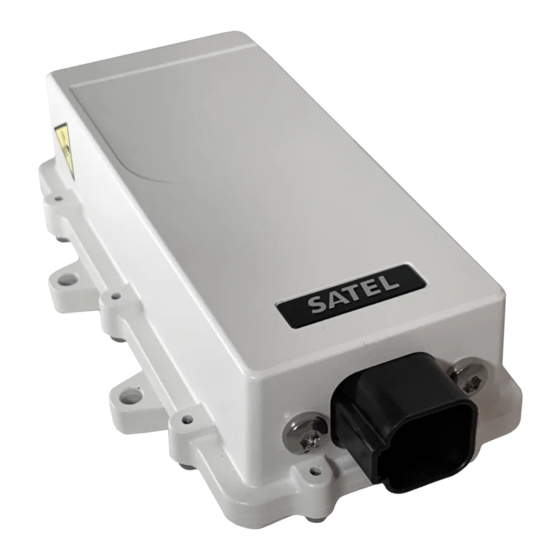
- Page 1 SATEL-TR4+ TRANSCEIVER MODULE INTEGRATION GUIDE Version 1.6...
-
Page 2: Important Notice
Integration Guide, Version 1.6 IMPORTANT NOTICE All rights to this manual are owned solely by SATEL Oy (referred to in this user guide as SATEL). All rights reserved. The copying of this manual (without the written permission from the owner) by... -
Page 3: Restrictions On Use - Satel-Tr4
Antenna Gain [dBi] Separation distance [cm] WARNING! Users of SATEL-TR4+ radio transceiver module in North America should be aware, that due to the allocation of the frequency band 406.0 – 406.1 MHz for government use only, the use of radio transceiver module on this frequency band without a proper permit is strictly forbidden. - Page 4 SATEL-TR4+ Integration Guide, Version 1.6 NOTE! According to the requirements of the FCC, the integrator should make sure that the SATEL-TR4+ is compliant to part 15C while integrated in the host device. Output power and spurious emissions should be verified.
-
Page 5: Product Conformity
Integration Guide, Version 1.6 PRODUCT CONFORMITY Under the sole responsibility of manufacturer SATEL Oy declares that SATEL-TR4+ radio transceiver module is in compliance with the essential requirements (radio performance, electromagnetic compatibility and electrical safety) and other relevant provisions of Directives 2014/53/EU and 2011/65/EU and Council recommendation 1999/519/EC. -
Page 6: Warranty And Safety Instructions
-The radio transceiver module is only to be operated at frequencies allocated by local authorities, and without exceeding the given maximum allowed output power ratings. SATEL and its distributors are not responsible, if any products manufactured by it are used in unlawful ways. -
Page 7: Host Integration
SATEL-TR4+ Integration Guide, Version 1.6 HOST INTEGRATION To ensure compliance with all non-transmitter functions the host manufacturer is responsible for ensuring compliance with the module(s) installed and fully operational. For example, if a host was previously authorized as an unintentional radiator under the Declaration of Conformity... -
Page 8: Table Of Contents
SATEL-TR4+ Integration Guide, Version 1.6 TABLE OF CONTENTS IMPORTANT NOTICE ..................... 1 RESTRICTIONS ON USE – SATEL-TR4+ ..............2 PRODUCT CONFORMITY ..................4 WARRANTY AND SAFETY INSTRUCTIONS ............. 5 HOST INTEGRATION ..................... 6 TABLE OF CONTENTS .................... 7 INTRODUCTION ..................10 Terms and abbreviations ................. - Page 9 Restart ...................... 26 CHANGING PARAMETERS USING SL COMMANDS ........ 27 SL Commands ................... 27 SL Command Mode .................. 28 DEFAULT DELIVERY VALUES – SATEL-TR4+ ..........29 CONSIDERATIONS .................. 30 EMI Interferers ..................30 Electrostatic discharge ................30 Using the device in unmanned high reliability applications ....31 PROPOSALS FOR MORE RELIABLE RADIO LINK ........
- Page 10 SATEL-TR4+ Integration Guide, Version 1.6 10.1 Module dimensions .................. 32 10.2 SL COMMANDS ..................32 VERSION HISTORY ................. 40...
-
Page 11: Introduction
European countries and also in many non-European countries. This document is the integration guide for the SATEL-TR4+ radio transceiver module. It is intended to describe how to use the module and how to integrate it into a host device. -
Page 12: Technical Specifications
SATEL-TR4+ Integration Guide, Version 1.6 2 TECHNICAL SPECIFICATIONS 2.1 Absolute maximum ratings Absolute maximum ratings for voltages on different pins are listed in the following table. Exceeding these values will cause permanent damage to the module. Parameter Voltage at VCC_IN... -
Page 13: Specifications, Satel-Tr4
SATEL-TR4+ Integration Guide, Version 1.6 2.3 Specifications, SATEL-TR4+ SATEL-TR4+ complies with the following international standards: EN 300 113 V2.2.1 (4FSK FEC ON and 8FSK FEC ON) EN 301 489-1 IEC 62368-1 RECEIVER TRANSMITTER Note! Frequency Range 403-473 MHz Tuning range... - Page 14 SATEL-TR4+ Integration Guide, Version 1.6 8FSK, 25 kHz, FEC typ. -36 dBm ON, BER = 10 8FSK, 12.5 kHz, FEC typ. -36 dBm ON, BER = 10 16FSK, 25 kHz, FEC typ. -44 dBm ON, BER = 10 16FSK, 12.5 kHz, typ.
- Page 15 SATEL-TR4+ Integration Guide, Version 1.6 DATA MODULE CMOS-UART Inputs and outputs referred to Electrical Interface IO Voltage processed by user (1.8-3.3V) RTS, CTS, RX, TX, +VCC, GND Samtec 20-pin through Interface Connector 1.27 mm pitch socket hole, CLP-110-02-L-D-K-TR Data speed of Serial 1200 –...
-
Page 16: Time Parameters For Startup And Shutdown Sequences
SATEL-TR4+ Integration Guide, Version 1.6 3 TIME PARAMETERS FOR STARTUP AND SHUTDOWN SEQUENCES The following table shows the recommend times for startup and shutdown sequences. Parameter Recom. Time Explanation >2 ms VCC_IN must be high before ENA_MOD is high vccin-ena >2 ms... -
Page 17: Shutdown And Ena Sequences
SATEL-TR4+ Integration Guide, Version 1.6 3.2 Shutdown and ENA sequences The following diagrams will describe the shutdown and ENA sequences. vccio-vccin VCC_IN ENA_MOD enamod-gpio VCC_IO gpio-vccio GPIOx_INPUT CTS1_OUT GPIOx_OUTPU T Figure 3.2 Shutdown sequence. VCC_IN ENA_MOD enamod-cts VCC_IO gpio-vccio GPIOx_INPUT... -
Page 18: Electrical Interconnection
SATEL-TR4+ Integration Guide, Version 1.6 4 ELECTRICAL INTERCONNECTION 4.1 DTE connector The DTE connector is a 20-pin pass-through connector. Connector is female two row 1.27 mm pitch. This connector allows the pin to enter the connector from the bottom side and protrude thru the module PCB to the top side, allowing flexible mounting heights with various pin lengths. -
Page 19: Pin Order Of The Dte Connector
SATEL-TR4+ Integration Guide, Version 1.6 4.2 Pin order of the DTE connector Direction IN is data from DTE (Data Terminal Equipment) to the radio transceiver module. Direction OUT is data from the radio module to the DTE. The equivalent I/O schematic figures are shown in the next chapter. -
Page 20: Equivalent I/O Schematics
SATEL-TR4+ Integration Guide, Version 1.6 4.3 Equivalent I/O Schematics The module input-output equivalent circuits are shown in the figure and the component values in the table below. Figure 1 Figure 2 Input Filter protection Input VCC_IO Filter with ESD protection... -
Page 21: Rf Interface
The setting and/or using of non-approved power levels may lead to prosecution. SATEL and its distributors are not responsible for any illegal use of its radio equipment, and are not responsible in any way of any claims or penalties arising from the operation of its radio equipment in ways contradictory to local regulations and/or requirements and/or laws. -
Page 22: Vcc_Io Pin
SATEL-TR4+ Integration Guide, Version 1.6 4.5 VCC_IO pin VCC_IO pin determines the voltage level of UART signals and the voltage level of GPIO output signals. VCC_IO level also determines GPIO LOW/HIGH levels on each GPIO and UART input pins. 4.6 Service pin The SERVICE pin is used to set the UART1 into a known state. -
Page 23: Uart Pins
SATEL-TR4+ Integration Guide, Version 1.6 4.9 UART pins Pins 7, 8, 9, 10 are used for UART serial transmission between the module and the terminal. The UART signal level corresponds to the level in VCC_IO pin. VCC_IO pin must be fed with a correct voltage level to match the terminal device. -
Page 24: Mechanical Considerations
SATEL-TR4+ Integration Guide, Version 1.6 5 MECHANICAL CONSIDERATIONS 5.1 Fixing device to host The radio transceiver module can be mounted on to the host application by using spacers and screws. It is highly recommended to use conducting metal spacers and screws to create proper electrical conductivity between the module and the host application. -
Page 25: Operating Modes
STAT pin in 250 ms interval indicating an Error and reboots the device after 5 s. Transmitting/Receiving is prohibited during malfunction. When connecting to the device with SATEL Configuration Manager the Error code is shown in pop up box. If the device does not recover after multiple reboots, please contact SATEL Oy. -
Page 26: Sleep Mode
SATEL-TR4+ Integration Guide, Version 1.6 6.3 Sleep Mode When being in sleep mode, the radio part of the module is switched OFF while the serial interface communication related parts remain powered ON. The module will be automatically woken up after the CPU senses a state change in the TD1 pin. Example: The module is in Sleep1- mode. -
Page 27: Restart
SATEL-TR4+ Integration Guide, Version 1.6 + 100 ms overlap marg RX slot, min marg RX slot, max overlap RX slot sleep marg overlap Figure 6.1 Power save mode timing factors. E.g. In system with TX interval of 1 s, and with 300 ms (approx. 300B @ 9600 bps) transmission... -
Page 28: Changing Parameters Using Sl Commands
CR/LF characters are added to end the response messages (unless they are already present) in order to make parsing easier. Settings can be toggled, SL Commands ON/OFF, CR/LF ON/OFF. The SL commands are listed in appendix 10. In order to get information of the latest and/or special SL commands please contact SATEL. -
Page 29: Command Mode
SL commands can be enabled or disabled by using the below described procedure. Regardless of original SL command –setting state, changing the setting state with this procedure will effect to the reception process of the radio module. SL command –setting state can be changed only via SATEL Configuration Manager in maintenance access level. -
Page 30: Default Delivery Values - Satel-Tr4
SATEL-TR4+ Integration Guide, Version 1.6 8 DEFAULT DELIVERY VALUES – SATEL-TR4+ DEFAULT VALUES OF THE ADJUSTABLE SETTINGS (the user can change these settings later on) Setting Default value Range Radio frequency Operating TX and RX 438.000 MHz 403 - 473 MHz... -
Page 31: Considerations
UHF band of interest. Number one is to recognize this challenge and act upon it. SATEL R&D can help in this by participating in design review of the host device, aiming to catch problems early in the design phase. -
Page 32: Using The Device In Unmanned High Reliability Applications
SATEL-TR4+ Integration Guide, Version 1.6 protection. The DTE port also features ESD protection diodes, but is not designed to withstand similar performance as expected from standalone units with enclosures. Consequently, the module should be subject to ESD handling precautions that typically apply to ESD sensitive components. -
Page 33: Appendix
SATEL-TR4+ Integration Guide, Version 1.6 10 APPENDIX 10.1 Module dimensions 10.2 SL COMMANDS Category Command Description Response Addressing SL#A? Show all addresses (RX1, RX2, TX1, "xxxx,yyyy,zzzz,vvvv" TX2) Addressing SL#A=xxxx, Set RX/TX addresses (RX1, RX2, "OK" or "ERROR" yyyy, zzzz,vvvv TX1, TX2) - Page 34 SATEL-TR4+ Integration Guide, Version 1.6 Addressing SL#P? Get primary transmit address (TX1) "xxxx;yyyy" and primary receive address (RX1) Addressing SL#P=xxxx;yyyy Set primary transmit address (TX1) "OK" or "ERROR" to value xxxx and primary receive address (RX1) to value yyyy [0000..ffff]...
- Page 35 SATEL-TR4+ Integration Guide, Version 1.6 ChannelList SL$F=n Set modem to channel number n in "OK" or "ERROR" channel list ChannelList SL$L?nn Get channel info. Channel number, Index nn=[0...(number of Frequency, Channel width, channels-1)] Tx Power For example: "CH 1, 430.150000 MHz, 25.0 kHz, 100 mW\0D"...
- Page 36 SATEL-TR4+ Integration Guide, Version 1.6 DataPort SL%B=a,b,c,d Set serial data port parameters. "OK" or "ERROR" a= "115200", "57600", "38400", "19200", "9600", "4800", "2400" or "1200" (defines baud rate) b="8" (defines character length) c= "N", "O" or "E" (defines parity) d= "1" (defines number of stop...
- Page 37 SATEL-TR4+ Integration Guide, Version 1.6 RadioFreq SL!D? Get lower limit of frequency band "nnn.nnnnn MHz" RadioFreq SL!U? Get upper limit of frequency band "nnn.nnnnn MHz" RadioFreq SL!W? Get lower limit of frequency band "nnn.nnnnn MHz" RadioFreq SL!Y? Get upper limit of frequency band "nnn.nnnnn MHz"...
- Page 38 List of numbers, separated modes. by commas, showing the supported modes: 0=Satel3AS, 1=PacCrest 4FSK, 2=PacCrest GMSK, 3=TrimTalk, 4=TrimTalk Trimble, 5=PCC FST, 6=2ASxE, 20=SATEL- 8FSK-1, 21=SATEL-8FSK- 2, 22=SATEL-16FSK-1 For example: "0,1" indicates that the modem supports Satel3AS and PacCrest 4FSK protocols. RadioProperty...
- Page 39 3 = TrimTalk450s(P) (Rx fits PacCrest modems) 4 = Trimtalk450s(T) (Rx fits Trimble modems) 5 = PacCrest-FST 6 = 2ASxE 20 = SATEL-8FSK-1 (FEC OFF) 21 = SATEL-8FSK-2 (FEC ON) 22 = SATEL-16FSK-1 (FEC Radio Property SL&P? Get TX/RX priority.
- Page 40 SATEL-TR4+ Integration Guide, Version 1.6 Operational SL++O Enable radio transmission / “OK” or “ERROR” mode reception Operational SL%N=1 Set enabled radio states Tx/Rx “OK” or “ERROR” mode Operational SL%N=0 Set enabled radio states Rx only “OK” or “ERROR” mode Operational...
- Page 41 SATEL-TR4+ Integration Guide, Version 1.6 11 VERSION HISTORY Version history: Version: Date: Remarks: 28.10.2019 First Draft. 23.03.2020 Updated mechanical drawing, section 5.3 removed and section 10.1 added. 24.03.2020 Several minor corrections and updates. 25.03.2020 First official release. 18.05.2020 Updated chapter 2.3 09.06.2020...
Need help?
Do you have a question about the SATEL-TR4+ and is the answer not in the manual?
Questions and answers