Table of Contents
Advertisement
Available languages
Available languages
Quick Links
NATURAL GAS MODELS:
PROPANE GAS MODELS:
SAFETY INFORMATION
WARNING
!
FIRE OR EXPLOSION HAZARD
Failure to follow safety warnings exactly
could result in serious injury, death, or
property damage.
- Do not store or use gasoline or other
fl ammable vapors and liquids in the vicinity of
this or any other appliance.
- WHAT TO DO IF YOU SMELL GAS:
•
Do not try to light any appliance.
•
Do not touch any electrical switch; do not
use any phone in your building.
•
Immediately call your gas supplier from a
neighbour's phone. Follow the gas
supplier's instructions.
•
If you cannot reach your gas supplier, call
the fi re department.
- Installation and service must be
performed by a qualifi ed installer, service
agency, or the supplier.
This appliance may be installed in an aftermarket,
permanently located, manufactured home (USA
only) or mobile home, where not prohibited by
local codes.
This appliance is only for use with the type of gas
indicated on the rating plate. This appliance is
not convertible for use with other gases, unless
a certifi ed kit is used.
INSTALLER:
Leave this manual with the appliance
CONSUMER:
Retain this manual for future reference
Wolf Steel Ltd., 24 Napoleon Rd., Barrie, ON, L4M 0G8 Canada / 103 Miller Drive, Crittenden, Kentucky, USA, 41030
$10.00
GDS28-1NSB / GDS28-1NE / GS28-1N / GS28-1NE
ADD PRODUCT CODE HERE (TRADE GOTHIC LT STD FONT)
GDS28-1PSB / GDS28-1PE / GS28-1P / GS28-1PE
Phone 1 (866) 820-8686 • www.napoleon.com • hearth@napoleon.com
INSTALLATION AND
ADD MANUAL TITLE
OPERATION MANUAL
Model GS28 is made up of Model GDS28 and
Natural Vent Adapter Kit GS-150KT
CERTIFIED TO THE CANADIAN AND AMERICAN NATIONAL STANDARDS:
CSA 2.22 AND ANSI Z21.50 FOR VENTED DECORATIVE GAS APPLIANCES
IF INSTALLATION + OPERATION, ADD SERIAL
CSA /
INTERTEK
BARCODE LABEL ON THE OWNER'S MANUAL"
LOGO
Product Name / Code
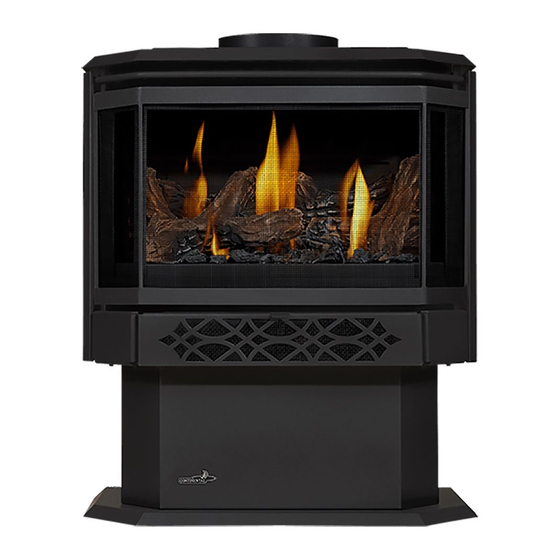
Haliburton™
(MUST use title from Price Book)
ADD ____ ILLUSTRATED
ADD PRODUCT IMAGE
FOR INDOOR USE ONLY
NUMBER LABEL HERE
IF SEPARATE MANUALS, ADD "PLACE
ENGLISH
FRENCH PG. 55
(GDS28-1 illustrated)
W415-2339 / B / 01.23.20
Advertisement
Chapters
Table of Contents
Troubleshooting

Related Manuals for Wolf Steel Napoleon Haliburton GDS28-1NSB

Summary of Contents for Wolf Steel Napoleon Haliburton GDS28-1NSB
- Page 1 INTERTEK BARCODE LABEL ON THE OWNER’S MANUAL” LOGO Wolf Steel Ltd., 24 Napoleon Rd., Barrie, ON, L4M 0G8 Canada / 103 Miller Drive, Crittenden, Kentucky, USA, 41030 Phone 1 (866) 820-8686 • www.napoleon.com • hearth@napoleon.com $10.00 W415-2339 / B / 01.23.20...
- Page 2 safety information WARNING • This appliance is hot when operated and DANGER can cause severe burns if contacted. • Any changes or alterations to this appliance or its controls can be dangerous and is prohibited. HOT GLASS WILL CAUSE • Do not operate appliance before reading and BURNS.
- Page 3 • If applicable, the millivolt version of this appliance uses and requires a fast acting thermocouple. Replace only with a fast acting thermocouple supplied by Wolf Steel Ltd. WARNING: This product can expose you to chemicals including lead and lead compounds,...
-
Page 4: Table Of Contents
/ remote (millivolt) note: The information throughout this manual is believed to be correct at the time of printing. Wolf Steel Ltd. reserves the right to change or modify any information within this manual at any time without notice. Changes, other than editorial, are denoted by a vertical line in the margin. -
Page 5: General Information
standard checklist Installer, please fi ll out the following information: Customer: _____________________________________________________________________ Address: _____________________________________________________________________ Date of Installation: _____________________________________________________________________ Location of Appliance: _____________________________________________________________________ Installer: _____________________________________________________________________ Dealer/Distributor Contact Number: _____________________________________________________________________ Serial #: _____________________________________________________________________ Model: Natural Gas: Propane: GDS28-1NSB GDS28-1PSB GS28-1N GS28-1P GDS28-1NE GDS28-1PE GS28-1NE GS28-1PE... -
Page 6: General Instructions
general information general instructions WARNING • Always light the pilot, whether for the fi rst time or if the gas supply has run out, with the glass door opened or removed. • Provide adequate clearance for servicing and operating the appliance. •... -
Page 7: Rating Plate Information
XXXX Serial Number / N° de Série: Electrical rating: 115V, 60HZ. Less than 12 amperes. Spécifications électriques: 115V, 60HZ. Moins de 12 ampère. WOLF STEEL LTD. 24 Napoleon Road, Barrie, ON, L4M 0G8 Canada W385-XXXX note: The rating plate must remain with the appliance at all times. It must not be removed. -
Page 8: Dimensions
general information dimensions W415-2339 / B / 01.23.20... -
Page 9: Venting
Mill Pac. High temperature sealant must be ordered separately. When using Wolf Steel venting components, use only approved Wolf Steel termination kits: wall terminal kit GD- 175 (7/12" of venting included), or 1/12 to 7/12 pitch roof terminal kit GD-110, 8/12 to 12/12 roof terminal kit GD- 111, fl... -
Page 10: Typical Vent Installation
venting These vent kits allow for either horizontal or vertical venting of the appliance. The maximum allowable horizontal run is 20 feet (6.1m). The maximum allowable vertical vent length is 40 feet (12.2m). The maximum number of vent connections is two horizontally or three vertically (excluding the appliance and the air terminal connections) when using fl... -
Page 11: Special Vent Installations
venting special vent installations 2.2.1 periscope termination Use the periscope kit to locate the air termination above grade. The periscope must be installed so that when fi nal grading is completed, the bottom air slot is located a minimum 12” (305mm) above grade. The maximum allowable vent length (including both rise and run) is 10’... -
Page 12: Vent Terminal Clearances
venting vent terminal clearances Covered balcony applications ††* = 3 feet = 2 x ACTUAL (0.9m) (4.6m) note: INSTALLATIONS Wall terminals are for illustration purposes only. Size and shapes may vary. CANADA U.S.A. 12” (30.5cm) 12” (30.5cm) Clearance above grade, veranda porch, deck or balcony. 12”... -
Page 13: Vent Fl Ow Charts
venting vent fl ow charts Top Exit Horizontal Termination Vertical Termination Vertical rise is equal Vertical rise is equal Vertical rise is less Vertical rise is less to or greater than the to or greater than the than horizontal run than horizontal run horizontal run horizontal run... -
Page 14: Horizontal Termination
venting horizontal termination ) < (V Simple venting confi guration (only one 90° elbow) See graph to determine the required vertical rise V for the required horizontal run H 40 (12.2) 39 (11.9) REQUIRED 30 (9.1) VERTICAL RISE IN FEET 20 (6.1) (METERS)V 10 (3.1) - Page 15 venting ) > (V Simple venting configuration (only one 90° elbow) See graph to determine the required vertical rise V the required horizontal run H 150 (3810) 147 (3733.8) REQUIRED VERTICAL RISE IN INCHES 100 (2540) (MILLIMETERS) V 57 (1447.8) 50 (1270) 29 (736.6) 20 (6.1)
-
Page 16: Top Exit Vertical Termination
venting top exit vertical termination ) < (V Simple venting configurations. See graph to determine the required vertical rise V for the required horizontal run H 40 (12.2) 30 (9.1) REQUIRED VERTICAL RISE IN FEET 20 (6.1) (METERS) V 10 (3.1) 3 (0.9) (1.5) (3.1) - Page 17 venting ) > (V Simple venting configurations. See graph to determine the required vertical rise V for the required horizontal run H 20 (6.1) 19 (5.8) REQUIRED VERTICAL RISE IN FEET 10 (3.1) (METERS) V 3 (0.9) (7.6) (9.1) (1.5) (3.1) (4.6) (6.1)
-
Page 18: Vertical Through Existing Chimney
COAXIAL TO The only exception to this rule is to use CO-LINEAR ADAPATOR Wolf Steel’s approved 3” (76.2mm) fl ex liner and co-linear termination. APPLIANCE VENT ADAPTOR * Measured from appliance fl ue collar to termination fl ue collar... -
Page 19: Installation
3.0 installation WARNING • Ensure to unpack all loose materials from inside the fi rebox prior to connecting the gas and electrical supply • If your appliance is supplied with a remote, ensure the remote receiver is in the “OFF” position prior to connecting the gas and electrical supply to the appliance. -
Page 20: Horizontal Installation
installation 3.1.1 horizontal installation WARNING • The fi restop assembly must be installed with the vent shield to the top. • Terminals must not be recessed into a wall or siding more than the depth of the return fl ange of the mounting plate. -
Page 21: Vertical Installation
B. Apply a bead of caulking (not supplied) to the framework or to the Wolf Steel vent pipe shield plate or equivalent (in the case of a fi nished ceiling), and secure over the opening in the ceiling. A fi restop must be... -
Page 22: Vertical Air Terminal Installation
installation 3.1.4 vertical air terminal installation WARNING • Maintain a minimum 2” (51mm) space between the air inlet base and the storm collar. note: Fastening hardware provided with appropriate roof terminal and liner kits. Fasten the roof support to the roof using 6 screws. The roof support is optional. -
Page 23: Appliance Vent Connection
installation appliance vent connection Attach the adjustable pipe to the last section of rigid pipe. Secure with screws and seal. #8 X 1/2” Self Drilling Install the inner fl ex pipe to the appliance. Secure with a minimum of Screws INSERT three screws and fl... -
Page 24: Installing Natural Vent
installation 3.3.3 installing natural vent Follow the instructions of the natural vent manufacturer for chimney installation. Remove and discard the two combustion air cover plates and gaskets located on the rear panel of the appliance. Replace the four screws per side to secure the rear panel to the appliance. -
Page 25: Adding Vent Sections
installation 3.3.5 adding vent sections Add chimney sections, according to the manufacturer’s installation instructions. If the chimney system passes through an attic space, a rafter radiation shield or attic insulation shield is required. The chimney must extend at least 3ft (0.9m) above its point of contact with the roof and at least 2ft (0.6m) higher than any wall, roof or building within 10ft (3.1m). -
Page 26: Gas Installation
4.0 gas installation WARNING • Risk of fi re, explosion, or asphyxiation. Ensure there are no ignition sources such as sparks or open fl ames. • Support gas control when attaching gas supply pipe to prevent damaging gas line. • Always light the pilot whether for the fi... -
Page 27: Safety Screen Installation And Removal
6.0 fi nishing WARNING • Risk of fi re! • Never obstruct the front opening of the appliance. • The front of the appliance must be fi nished with any non-combustible materials such as brick, marble, granite, etc., provided that these materials do not go below the specifi ed dimension, as illustrated. •... -
Page 28: Door Closing And Opening
fi nishing door closing and opening WARNING • Glass may be hot. Do not touch glass until cooled. • If equipped with door latches that are part of a safety system, they must be properly engaged. Do not operate the appliance with latches disengaged. •... -
Page 29: Log Placement
The logs are fragile and should be handled with care. PHAZER logs, glowing embers, and charcoal embers, exclusive to Wolf Steel Ltd., glow when exposed to direct fl ame, and provide a unique and realistic glowing effect that is different in every installation. Use only certifi ed PHAZER™... -
Page 30: Glowing Embers
fi nishing glowing embers WARNING • Completely blocking the burner ports can cause an incorrect fl ame pattern, carbon deposits and delayed ignition. Tear the embers into pieces and loosely layer above the burner ports covering the burner area. Care should be taken to shred the embers into thin, small irregular pieces as only the exposed edges of the fi... -
Page 31: Operating Instructions
7.0 operating instructions operation (electronic) operating/lighting instructions The on-off switch is located on the back of the appliance at the top left corner on models GDS28 and GS28. When lit for the fi rst time, the appliance will emit a slight odour for a few hours. This is a normal temporary condi- tion caused by the "burn-in"... -
Page 32: Wiring Diagram (Electronic) Operation (Electronic)
8.0 wiring diagram (electronic) operation (electronic) WARNING • Do not wire 110 volts to the valve or wall switch. note: This appliance comes equipped with a battery back-up. If this back-up is used, install 4 ‘AA’ batteries (not supplied) into the holder and connect to the wire harness. Connect the battery holder to the wire harness before using the appliance. - Page 33 9.0 operation (electronic) operation (electronic) WARNING • If you do not follow these instructions exactly, a fi re or explosion may result causing property damage, personal injury, or loss of life. • If applicable, always light the pilot whether for the fi rst time or if the gas supply has run out with the glass door opened or removed.
-
Page 34: Pilot-On-Demand
operation (electronic) ADD TITLE: PILOT-ON-DEMAND pilot-on-demand This appliance is equipped with an “On Demand” intermittent pilot ignition system (IPI) which also includes a continuous pilot ignition (CPI) mode with an integrated seven day timer. This system minimizes your appliance’s carbon footprint as well as reducing its annual fuel consumption and operating costs. In IPI mode, the pilot will ignite prior to the main burner, when the appliance is turned on using a switch, remote or from a call for heat with the thermostat (if equipped). -
Page 35: Operation (Millivolt)
10.0 operation (millivolt) operation (millivolt) WARNING • If you do not follow these instructions exactly, a fi re or explosion may result causing property damage, personal injury, or loss of life. • If applicable, always light the pilot whether for the fi rst time or if the gas supply has run out with the glass door opened or removed. -
Page 36: Pilot Burner Adjustment
11.0 adjustment 11.1 pilot burner adjustment Adjust the pilot screw to provide properly sized fl ame. Turn in a clockwise direction to reduce the gas fl ow. PILOT ELECTRODE Check Pressure Readings: BURNER 3/8” - 1/2” Inlet pressure can be checked by turning screw (A) counter- (9.5mm - 12.7mm) FLAME ELECTRONIC... -
Page 37: Venturi Adjustment
11.2 venturi adjustment This appliance has an air shutter that has been factory set open according to the chart below: VENTURI Regardless of venturi orientation, closing the air shutter will cause a more BURNER yellow flame, but can lead to carbonization. Opening the air shutter will cause a more blue flame, but can cause flame lifting from the burner ports. - Page 38 12.0 maintenance WARNING • Turn off the gas and electrical power before servicing the appliance. • Appliance may be hot. Do not service until appliance has cooled. • Do not use abrasive cleaners on glass. • Do not paint the pilot assembly. This appliance and its venting system should be inspected before use and at least annually by a qualifi...
-
Page 39: Annual Maintenance
maintenance 12.1 annual maintenance WARNING • Annual maintenance should be performed by a qualifi ed service technician • The fi rebox becomes very hot during operation. Let the appliance cool completely or wear heat resistant gloves before conducting service. • Never vacuum hot embers. -
Page 40: Blower Replacement
maintenance 12.3 blower replacement Blower replacement may be done through either the fi rebox or from the rear of the appliance. Using the rear panel is recommended. BLOWER INSTALLATION THROUGH THE REAR PANEL : FOR MODEL GDS28 white • Turn off the electrical power and the gas supply to the appliance. THERMAL •... -
Page 41: Replacement Parts
13.0 replacement parts WARNING • Failure to position the parts in accordance with this manual or failure to use only parts specifi cally approved with this appliance may result in property damage or personal injury. Contact your dealer for questions concerning prices and policies on replacement parts. Normally, all parts can be ordered through your Authorized dealer / distributor. -
Page 42: Overview
replacement parts W415-2339 / B / 01.23.20... -
Page 43: Millivolt Valve Train Assembly
replacement parts W415-2339 / B / 01.23.20... -
Page 44: Electronic Valve Train Assembly
replacement parts W415-2339 / B / 01.23.20... - Page 45 14.0 accessories accessories W415-2339 / B / 01.23.20...
-
Page 46: Troubleshooting (Millivolt)
troubleshooting (millivolt) 15.0 troubleshooting (millivolt) WARNING • Always light the pilot whether for the fi rst time or if the gas supply has run out, with the glass door open or removed. • Turn off gas and electrical power before servicing the appliance. •... - Page 47 troubleshooting (millivolt) symptom problem test solution Exhaust fumes smelled Appliance is spilling. Check door seal. in room, headaches. (This is not applicable in outdoor Check for exhaust damage. appliances) Check that venting is installed correctly. Room is in negative pressure; increase fresh air supply. Exhaust fumes smelled Appliance is spilling.
- Page 48 troubleshooting (millivolt) symptom problem test solution Door Sticking Dirt / dust adheres to the hinges; Lift door from its hinges. Lubricate with high temp dry is heated and burns causing graphite only. Replace. sticking. NOTE: Due to the high temperatures that the hinges experience, wet lubricants such as oil and WD40 will cause the hinge to seize and are therefore not suitable.
-
Page 49: Troubleshooting (Electronic)
16.0 troubleshooting (electronic) troubleshooting (electronic) WARNING • Always light the pilot whether for the fi rst time or if the gas supply has run out, with the glass door open or removed. • Turn off gas and electrical power before servicing the appliance. •... - Page 50 troubleshooting (electronic) symptom problem test solution Pilot will not light. Makes Wiring: short, loose, or damaged Verify the thermocouple/sensor is clean and the wiring is undamaged. Verify the interrupter block is not damaged or too tight. Verify noise with no spark at connections connections from pilot assembly are tight;...
- Page 51 troubleshooting (electronic) symptom problem test solution Lights or blower Control module switch in Verify ON/OFF switch is in the “I” position which denotes on. won’t function (if wrong position. equipped). COM switch is unplugged. Verify “COM” switch is plugged into the front of the control module.
- Page 52 All specifi cations and designed are subject to change without prior notice due to on-going product improvements. Napoleon is a registered trademark of Wolf Steel Ltd. W415-2339 / B / 01.23.20...
-
Page 53: Service History
18.0 service history service history W415-2339 / B / 01.23.20... - Page 54 NAPOLEON CELEBRATING OVER 40 YEARS OF HOME COMFORT PRODUCTS 7200, Route Transcanadienne, Montréal, Québec H4T 1A3 24 Napoleon Road, Barrie, Ontario, Canada L4M 0G8 214 Bayview Drive, Barrie, Ontario, Canada L4N 4Y8 Scan this QR code for more information or visit our website at: Scan fo for more...
- Page 55 IF SEPARATE MANUALS, ADD “PLACE LOGO BARCODE LABEL ON THE OWNER’S MANUAL” Wolf Steel Ltd., 24 Napoleon Rd., Barrie, ON, L4M 0G8 Canada / 103 Miller Drive, Crittenden, Kentucky, USA, 41030 Téléphone 1(866)820-8686 • www.napoleon.com • hearth@napoleon.com $10.00 W415-2339 / B / 01.23.20...
- Page 56 consignes de sécurité AVERTISSEMENT • Cet appareil est chaud lorsqu’il AVERTISSEMENT fonctionne et peut causer de graves brûlures en cas de contact. • Toute modifi cation apportée à cet appareil ou aux contrôles peut être LA VITRE CHAUDE CAUSERA dangereux et est interdit. DES BRÛLURES.
- Page 57 • S’il y a lieu, la version de millivolt de cet appareil utilise et requiert un thermocouple à action rapide. Remplacez uniquement par un thermocouple à action rapide de Wolf Steel ltée. AVERTISSEMENT: Ce produit peut vous exposer à des substances chimiques incluant le Add California Prop 65 warning plomb et les composés de plomb qui, selon l’État de Californie, causeraient le cancer, et des...
- Page 58 3.3.5 ajout de sections d'évents note: L’information contenue dans ce manuel est jugée correcte au moment de l’impression. Wolf Steel Ltée. se réserve le droit de modifi er ou de modifi er toute information contenue dans ce manuel à tout moment sans préavis.
-
Page 59: Information Générales
liste de vérifi cation Installateur, veuillez rempli les informations suivants: Client: _____________________________________________________________________ Addresse: _____________________________________________________________________ Date d'installation: _____________________________________________________________________ Location de l'appareil: _____________________________________________________________________ Installateur: _____________________________________________________________________ Numéro de contact du détaillant / distributeur: _____________________________________________________________________ No. de série: _____________________________________________________________________ Modèle: GDS28-1NSB GDS28-1PSB Gaz naturel: Propane: GS28-1N GS28-1P... -
Page 60: Information Générales
PSIG (35mb) ou moins. • N’utilisez que les accessoires optionnels et les pièces de rechange approuvés par Wolf Steel pour cet appareil. L’utilisation d’accessoires non listés (souffl eries, portes, persiennes, moulures, composants de gaz, composants d’évacuation, etc.) pourrait être non sécuritaire et annulera la garantie et la certifi cation. -
Page 61: Information Sur La Plaque
Serial Number / N° de Série: Electrical rating: 115V, 60HZ. Less than 12 amperes. Spécifications électriques: 115V, 60HZ. Moins de 12 ampère. W385-XXXX WOLF STEEL LTD. 24 Napoleon Road, Barrie, ON, L4M 0G8 Canada Road, oad, NOTE: La plaque d'homologation doit rester avec l'appareil tout le temps. Elle ne doit pas être retiré. -
Page 62: Dimensions
information générales dimensions W415-2339 / B / 01.23.20... -
Page 63: Évacuation
Les courses horizontales et verticales du système doivent être supportées à tous les 3 pi (0,9m). Utilisez l’ensemble de support mural Wolf Steel W010-0067 ou des attaches incombustibles équivalents afi n de maintenir le dégagement aux matériaux combustibles pour les courses verticales et horizontales. Des espaceurs sont fi... -
Page 64: Installations Typiques D'évents
évacuation Lorsque vous utilisez les composants d'évacuation Wolf Steel, n'utilisez que des composants d'évacuation Wolf Steel conjointement avec les ensembles de terminaison suivants: ensemble de terminaison murale GD-175 (7/12" de conduits inclus), ou ensemble de terminaison pour toit de pente 1/12 à 7/12 GD-110, ensemble de termi- naison pour toit de pente 8/12 à... -
Page 65: Installations Particulières D'évents
évacuation installations particulières d'évents 2.2.1 ensemble périscopique Utilisez l’ensemble périscopique afi n de positionner la terminaison au-dessus du niveau du sol. L’ensemble périscopique doit être installé de façon à ce que la fente d’air du bas soit située à un minimum de 12 pouces (305mm) au-dessus du niveau du sol. -
Page 66: Emplacements Et Dégagements Minimaux De La Terminaison
évacuation emplacements et dégagements minimaux de la terminaison Applications pour balcon couvert ††* = 3 feet = 2 x ACTUAL (0.9m) (4.6m) note: INSTALLATIONS Les terminaux du mur sont à des fi ns d’illustration seulement. La taille et les formes peuvent varier. CANADA É.-U. -
Page 67: Charte D'application Des Évacuations
évacuation charte d'application des évacuations Évacuation sur le dessus Terminaison horizontale Terminaison verticale La course verticale est La course verticale La course verticale La course verticale plus grande ou égale à est plus petite que la est plus grande ou est plus petite que la la course horizontale course horizontale... -
Page 68: Évacuation Sur Le Dessus - Terminaison
évacuation évacuation sur le dessus - terminaison horizontale ) < (V Confi guration d’évacuation simple Consultez le graphique pour déterminer la course verticale nécessaire V par rapport à la (un coude de 90° seulement). course horizontale requise H 40 (12,2) 39 (11,9) COURSE 30 (9,1) - Page 69 évacuation ) > (V Consultez le graphique pour déterminer la course verticale Configuration d'évacuation simple (un coude de 90° nécessaire V par rapport à la course horizontale requise H seulement). 150 (3810) 147 (3733,8) COURSE VERTICALE 100 (2540) REQUISE EN POUCES (MILLIMÈTRES)V 57 (1447,8)
- Page 70 évacuation évacuation sur le dessus - terminaison verticale ) < (V Configuration d'évacuation simple. Consultez le graphique pour déterminer la course verticale nécessaire V par rapport à la course horizontale requise H 40 (12,2) 30 (9,1) COURSE VERTICALE REQUISE EN 20 (6,1) PIEDS (MÈTRES)V...
- Page 71 évacuation ) > (V Configuration d'évacuation simple. Consultez le graphique pour déterminer la course verticale nécessaire V par rapport à la course horizontale requise H 20 (6,1) 19 (5,8) COURSE VERTICALE REQUISE EN 10 (3,1) PIEDS (MÈTRES) V 3 (0,9) (1,5) (3,1) (4,6)
-
Page 72: Terminaison Verticale À Travers Une
La seule exception à cette règle est l’usage du ADAPTATEUR D'ÉVENT DE L'APPAREIL système de conduit fl exible de 3” (7,6cmm) et de terminaison colinéaire Wolf Steel. * Mesurée à partir de la buse de l’appareil jusqu’au collet de la terminaison. -
Page 73: Dégagements Minimaux Aux Matériaux
3.0 installation installation AVERTISSEMENT • Avant d’effectuer les branchements pour l’alimentation en gaz et électronique, assurez-vous de retirer toute composante non fi xée à l’intérieur de la chambre de combustion. • Si votre appareil comprend un système de télécommande, assurez-vous que le récepteur est à la position «... -
Page 74: Installation Horizontale
installation note: Si l’appareil est installé directement sur un tapis, sur une surface de vinyle, ou tout autre revêtement de plancher combustible autre que le bois, l’appareil devra être monté sur 3.1.1 installation horizontale AVERTISSEMENT • L’espaceur coupe-feu doit être installé avec l’écran protecteur orienté vers le haut. •... -
Page 75: Installation Verticale
B. Appliquez un joint de calfeutrage (non fourni) sur la charpente ou sur Protecteur le protecteur de conduit d’évacuation Wolf Steel ou l’équivalent (dans Calfeutrage du conduit le cas d’un plafond fi ni) et fi xez le protecteur de conduit d’évacuation d’évacuation... -
Page 76: Installation De La Terminaison Verticale
installation 3.1.4 installation de la terminaison verticale AVERTISSEMENT • Conservez un espace minimale de 2 po (51mm) entre la base de la prise d’air et le collet de solin. Matériel de fi xation fourni avec les ensembles de terminal pour toit et raccord appropriées. Fixez le support de toit au toit à... -
Page 77: Raccordement Des Évents À L'appareil
installation raccordement des évents à l'appareil Attachez le tuyau télescopique à la dernière section de conduit rigide. Fixez-le avec des vis et scellez. #8 X 1/2” Fixez-la à l’aide d’au moins trois vis et rondelles lorsque vous autoperceuses INSERT 2” (50.8mm) utilisant une évent de 3”/5”, 4”/7”... -
Page 78: Installation De L'évent De Type " B
installation 3.3.3 installation de l'évent de type « B » Suivez les instructions du fabricant de l'évent de type « B » pour l'installation de la cheminée. Enlevez et jetez les deux plaques couvrant les entrées d'air comburant, ainsi que leur joint d'étanchéité, qui se trouvent sur le panneau arrière de l'appareil. -
Page 79: Ajout De Sections D'évents
installation 3.3.5 ajout de sections d'évents Ajoutez des sections de cheminée, selon les instructions d’installation du fabricant. Si la cheminée devra dépasser par l’espace grenier un écran protecteur de chevrons ou une bouclier d'isolation du grenier est requis. La cheminée doit dépasser le toit d’au moins 3’... -
Page 80: Branchement Du Gaz
4.0 branchement du gaz installation AVERTISSEMENT • Risque d’incendie, d’explosion, ou d’asphyxie. Assurez-vous qu’il n’y ait aucune source d’allumage comme des étincelles ou une fl amme nue. • Soutenez le contrôle du gaz lorsque vous attachez le tuyau pour éviter de plier la conduite de gaz. •... -
Page 81: Finitions
6.0 fi nitions fi nitions AVERTISSEMENT • Risque d’incendie! • N’obstruez jamais l’ouverture sur le devant de l’appareil. • La façade de l’appareil doit être faite de matériaux incombustibles comme de la brique, du marbre, du granite, etc., à condition que ces matériaux ne se trouvent pas en deçà de la dimension spécifi ée tel qu’illustré. Comme alternative, vous pouvez utiliser le panneau de gypse comme fi... -
Page 82: Ouverture Et Fermeture De La Porte
fi nitions ouverture et fermeture de la porte AVERTISSEMENT • La vitre peut être chaude. Ne touchez pas la vitre jusqu’à ce qu’elle ait refroidi. • Les loquets de porte font partie d’un dispositif de sécurité et doivent être adéquatement verrouillés. Ne faites pas fonctionner l’appareil lorsque les loquets sont déverrouillés. -
Page 83: Disposition Des Bûches
, les braises incandescentes et les braises de charbon de bois, exclusives aux appareils Wolf Steel ltée, sont incandescentes lorsqu’elles sont exposées à une fl amme directe et créent un effet incandescent réaliste et unique qui est différent dans chaque installation. N’utilisez que les bûches, les braises incandescentes et les braises de charbon de bois certifi... -
Page 84: Braises Incandescentes
fi nitions braises incandescentes AVERTISSEMENT • Obstruez pas ni fermer les orifi ces du brûleur. Le blocage des orifi ces du brûleur peut créer une fl amme irrégulière, des dépôts de carbone et un retard d’allumage. Déchirez les braises incandescentes en morceaux et placez une couche lâche sur le grillage du brûleur. Les braises devraient être déchirées très soigneusement en petits morceaux minces irréguliers, car seuls les côtés des fi... -
Page 85: Instructions D'opération
7.0 instructions d'opération fi nitions instructions d'opération / allumage L’interrupteur marche/arrêt des modèles GDS28 et GS28 est situé à l’arrière de l'appareil, dans le coin supérieur gauche. Lorsqu’il est allumé pour la première fois, l'appareil dégagera une légère odeur pendant quelques heures. Cela est une condition normale temporaire causée par la cuisson de la peinture et l’évaporation des lubrifi... -
Page 86: Schéma De Câblage (Électronique)
8.0 schéma de câblage (électronique) fi nitions AVERTISSEMENT • Ne raccordez pas l'interrupteur mural ou la soupape de gaz à l'alimentation électrique (110V). note: Cet appareil est équipé avec une sauvegarde de pile. Si le sauvegarde de pile est utiliser, installez 4 piles « AA »... -
Page 87: Opération (Électronique)
9.0 opération (électronique) opération (électronique) AVERTISSEMENT • Si ces instructions ne sont pas suivies à la lettre, un incendie ou une explosion pourraient s’ensuivre, causant des dommages matériels, des blessures corporelles ou des pertes de vie. • Si applicable, allumez toujours la veilleuse, que ce soit pour la première fois ou lorsque l’approvisionnement en gaz est épuisé, avec la porte vitrée ouverte ou retirée. -
Page 88: Veilleuse Sur Demande
opération (électronique) ADD TITLE: VEILLEUSE SUR DEMANDE veilleuse sur demande Cet appareil est équipé d’un système de veilleuse à allumage intermittent (IPI) « Sur demande » qui comprend également un mode de veilleuse permanente (CPI) avec une minuterie intégrée de sept jours. Ce système minimise l’empreinte carbone de votre appareil et réduit sa consommation annuelle de combustible ainsi que son coût de fonctionnement. -
Page 89: Opération (Millivolt)
10.0 opération (millivolt) opération (millivolt) AVERTISSEMENT • Si ces instructions ne sont pas suivies à la lettre, un incendie ou une explosion pourraient s’ensuivre, causant des dommages matériels, des blessures corporelles ou des pertes de vie. • Allumez toujours la veilleuse, que ce soit pour la première fois ou lorsque l’approvisionnement en gaz est épuisé, avec la porte vitrée ouverte ou retirée Assurez-vous que l’arrivée de gaz au brûleur est continue avant de réinstaller la porte. -
Page 90: Réglages
11.0 réglages réglages 11.1 réglage de la veilleuse Ajustez la vis de la veilleuse pour obtenir une fl amme de taille normale. Tournez vers la droite pour réduire l’apport de gaz. PILOT ELECTRODE BURNER Vérifi ez la pression: 3/8" - 1/2" 3/8”... -
Page 91: Réglage Du Venturi
réglages 11.2 réglage du venturi L’ouverture du volet d’air a été préréglée en usine selon le tableau ci-dessous: Indépendamment de l’orientation du venturi, plus le volet est fermé, plus la VENTURI flamme est jaune et aura tendance à causer des dépôts de carbone. Plus le volet est ouvert, plus la flamme est bleue et plus elle a tendance à... -
Page 92: Entretien
12.0 entretien entretien AVERTISSEMENT • Coupez l’alimentation en gaz et l’alimentation électrique avant de procéder à l’entretien de l’appareil. • L’appareil peut être chaud. Attendez qu’il soit refroidi avant d’en faire l’entretien. • N’utilisez pas de produits abrasifs. • Ne peinture pas l’assemblage de la veilleuse. Cet appareil et son système d’évacuation devraient être inspectés avant la première utilisation et au moins une fois l’an par un technicien de service qualifi... -
Page 93: Entretien Annuel
entretien 12.1 entretien annuel AVERTISSEMENT • Le caisson devient trés chaud lors du fonctionnement. Laissez l’appareil se refroidir complétement ou portez des gants antichaleur avant d’effectuer l’entretien. • Ne jamais aspirer des braises qui sont chaudes. • Ne peinturez pas l’assemblage de la veilleuse. •... -
Page 94: Remplacement De La Souffl Erie
entretien 12.3 remplacement de la souffl erie SOUFFLERIE Le remplacement de la souffl erie peut être fait depuis la chambre de combustion ou depuis le panneau. Nous vous conseillons cette dernière option. INSTALLATION DEPUIS LE PANNEAU ARRIÈRE : blanc POUR LE MODÈLE GDS28 THERMODISQUE •... -
Page 95: Pièces De Rechange
pièces de rechange 13.0 pièces de rechange AVERTISSEMENT • Omettre de positionner les pièces conformément à ce manuel ou d’utiliser uniquement des pièces spécifi quement approuvées pour cet appareil peut causer des dommages matériels ou des blessures corporelles. Contactez votre détaillant pour les questions concernant les prix et la disponibilité des pièces de remplace- ment. -
Page 96: Vue D'ensemble
pièces de rechange W415-2339 / B / 01.23.20... -
Page 97: Assemblage De La Soupape Millivolt
pièces de rechange W415-2339 / B / 01.23.20... - Page 98 pièces de rechange W415-2339 / B / 01.23.20...
-
Page 99: Accessoires
pièces de rechange 14.0 accessoires W415-2339 / B / 01.23.20... -
Page 100: Guide De Dépannage (Millivolt)
guide de dépannage (millivolt) 15.0 guide de dépannage (millivolt) AVERTISSEMENT • Allumez toujours la veilleuse, que ce soit pour la première fois ou lorsque l’approvisionnement en gaz est épuisé, avec la porte vitrée ouverte ou retirée. • Coupez l’alimentation en gaz et l’alimentation électrique avant de procéder à l’entretien de l’appareil. •... - Page 101 guide de dépannage (millivolt) symptôme problème solutions Une pellicule blanche Le souffre du combustible se Nettoyez la vitre avec un nettoyeur recommandé. ou grise se forme. dépose sur la vitre, les bûches NE PAS NETTOYER LORSQU’ELLE EST CHAUDE. ou les parois de la chambre de Si vous ne nettoyez pas les dépôts régulièrement, la vitre risque de rester combustion.
- Page 102 guide de dépannage (millivolt) Interrupteur mural est L’interrupteur mural est monté à Inverse. en position « OFF »; l’envers. la brûleur s’allume Interrupteur mural est relié à Remplacez. lorsque le bouton la terre. d’allumage de gaz est tourné à la position Le fi ls de l’nterrupteur mural est Vérifi...
-
Page 103: Guide De Dépannage (Électronique)
guide de dépannage (électronique) 16.0 guide de dépannage (électronique) AVERTISSEMENT • Allumez toujours la veilleuse, que ce soit pour la première fois ou lorsque l’approvisionnement en gaz est épuisé, avec la porte vitrée ouverte ou retirée. • Coupez l’alimentation en gaz et l’alimentation électrique avant de procéder à l’entretien de l’appareil. •... - Page 104 guide de dépannage (électronique) symptôme problème solution La veilleuse ne s’allume Câblage: pénurie, connexion Vérifi ez qu’il n’y a pas de connexions desserrées du thermocouple ni sonde de fl amme. pas. Il y a du bruit mais desserrée (rectifi cation de la Vérifi...
- Page 105 guide de dépannage (électronique) symptôme problème solution Le télécommande ne La télécommande s’allume mais Réinitiliser en tourant l’alimentation « off » puis « on ». fonctionne pas cor- aucune étincelle ou fl amme. (La note: rectement. télécommande est verrouillé). Si les piles de sauvegarde sont installés, ils doivent être enlevées pour programmer le télécommande.
-
Page 106: Garantie
Les frais de déplacement, de tests de diagnostic, d’expédition et autres frais afférents ne sont pas couverts par cette garantie. Toutes les spécifi cations et les conceptions sont sujettes à modifi cations sans préavis en raison des améliorations constantes apportées au produit. Napoléon est une marque de commerce déposée de Wolf Steel Ltée. W415-2339 / B / 01.23.20... -
Page 107: Historique D'entretien
garantie 18.0 historique d'entretien W415-2339 / B / 01.23.20... - Page 108 NAPOLÉON CÉLÈBRE PLUS DE 40 ANS D’EXISTENCE É É É É É É É É É È È ’E XISTENCE CONSACRÉS À LA CONCEPTION DE PRODUITS DE CONFORT É É É É À À À T IO E PR ODUITS CONFORT 7200, Route Transcanadienne, Montréal, Québec H4T 1A3 24 Napoleon Road, Barrie, Ontario, Canada L4M 0G8...
Need help?
Do you have a question about the Napoleon Haliburton GDS28-1NSB and is the answer not in the manual?
Questions and answers
I have just had your Haliburton model installed in my home. I have turned on the gas fireplace with the remote control but I do not understand the IPI and CPI modes. I also do not know how to set the thermostat. Where can I find this info. I don't find your manual very user friendly
The Napoleon Haliburton GDS28-1NSB gas fireplace has two ignition modes:
- IPI (Intermittent Pilot Ignition): The pilot light ignites only when needed.
- CPI (Continuous Pilot Ignition): The pilot light remains on continuously.
To select between these modes:
- If your fireplace has an ACS switch, flipping it up or down will change the mode depending on how the switch is installed.
- If your fireplace has a remote control, refer to its instructions to select IPI or CPI.
To set the thermostat:
1. Ensure the thermostat is installed and operational.
2. Turn on all electrical power to the appliance.
3. Adjust the thermostat to the desired temperature setting.
This answer is automatically generated