Table of Contents
Advertisement
Quick Links
INSTALLATION INSTRUCTIONS AND HOLE-CUTTING TEMPLATE
MANROSE FAN6577
Halogen Heater Fan & Light
Dear customers,
Please read all instructions before commencing installation.
!
WARNING: Indicates that injury or death could occur if below
Warnings are not followed.
!
This unit must be installed to comply with the appropriate council
regulations and the Australia and New Zealand wiring rules
AS/NZS3000:2007 or lastest edition thereof.
All wiring must be carried out by a Licensed Electrician in accordance
!
with all applicable codes and standards.
Use this heater only as described in this manual. The manufacturer
!
does not recommend any other use as this may cause fire, electric
shock, or injury to persons. If you have questions, contact the
manufacturer or local agent.
!
Make sure the power is off before the installation.
The heaters glass shield is hot when in use. Do not touch the heat lamp
!
and glass shield with any part of your body when in use.
For the purpose of avoiding any dangerous gas leaking into your
!
bathroom, the duct vent of the heater must not be laid together with the
duct vent of air-fueled water heater or other open-fire appliances into
the same flue.
!
The heater is to be installed so that switches and other controls cannot
be touched by a person in the bath or shower.
This unit should not be installed directly above a shower or bathtub.
!
The unit must not be installed in a position where water may splash
onto the unit.
CAUTION: Possibility of damage to equipment, installation or premises
Cautions
if below
are not followed.
• The power cable of this product must withstand a minimum 10A
load.
• The main supply and interconnecting cables required for installation
of this unit are not included.
• This unit must be properly grounded.
• The disconnection of the product is achieved by incorporating a
switch in the fixed wiring in accordance with the wiring rules. The
heater must be isolated from the power by means of a disconnection
switch with a contact separation of at least 3mm.
Read and save these instructions!
• The appliance is not intended for use by persons (including children)
with reduced physical, sensory or mental capabilities, or lack of
experience and knowledge, unless they have been given supervision or
instruction concerning use of the appliance by a person responsible for
their safety.
• Children should be supervised to ensure that they do not play with the
appliance.
• The appliance shall, under no circumstances, be covered with insulating
material or similar material.
• Regulations concerning the discharge of air have to be fulfilled.
• The unit must not be installed beneath a fixed socket.
• The unit is designed for installation in flat ceilings only. Do not mount it
on a sloping ceiling or a vertical wall.
• Before commencing any cutting, check in the ceiling space that there are
no obstructions such as electrical wiring, hidden utilities or ceiling joists
and that there is sufficient height clearance for the housing. Check that
the electrical wiring can be routed from the wall switches to the mounting
location.
• Joists, beams and rafters shall not be cut or notched to install the
appliance.
INSTALLATION
A few minutes of planning can make a big difference to the installation
time and also to your satisfaction with the function of the unit.
1. Cutting a vent
Locate the exterior grill location on a wall or soffit, then cut a 155mm
diameter hole at this very position.
2. Ducting
Put one end of the 150mm diameter duct into the vent hole and connect to
grill or cowl with one duct clip included . A 150mm diameter egg-crate grille
is included in the package to be used when installing in soffit. If installed
in wall a weatherproof cowl should be used. Seal grille/cowl with suitable
sealant.
Note: The length of each duct is 3.0m. Make sure that from the centre of
installation position there should be a distance within 3.0m to the outside
vent.
3. Suitable location
The heater must be installed at least 2.1m above the floor and no more
than 2.4m from the ground. The heater is most effective when you are
standing directly beneath it, so generally the unit would be mounted in a
place where you would stand to dry yourself. For the exhaust fan to work
efficiently, replacement air of a volume equivalent to what is being
wall
duct clip
sealant ventiduct
bathroom
heater
fascia
ceiling
ceiling joist
Wall venting shown
extracted must be able to enter the room. Generally, this air would be
drawn under the door with a minimum space of 20mm. If the room is
airtight, the fan will function poorly.
4. Prepare the ceiling
Use this template to mark the hole outline on the ceiling. Make sure
a distance between the edges and wall is no less than 250mm. Also
from the rooftop should be a minimum 220mm height to the ceiling.
5. Remove the fascia
Remove 4 rubber clips at 2 ends of the rectangle air inlet grilles.
Remove
the
screws
hidden
behind. Remove the fascia.
Note:
Be careful while removing
the screws so that the fascia
Heater Unit
does not drop to the ground.
6. Disconnect
Power cables to LED Panel.
Remove the halogen heat lamp
Rubber clip
from the heater unit and keep it in
a safe place. Do not touch
this lamp with your bare skin.
Natural skin oils and salts damage new halogen lamps and
shorten their life. Only handle a new heat lamp with soft, dry, clean,
lint-free cloth or paper. You can wear gloves, cover your fingers or
wrap the heat lamp until it is installed (so long as you remove all cloth
or paper when finished).
7. Wiring
Connect one end of the interconnecting
wire with the switch panel, and then
drag the other end power cable out of
the hole on the ceiling. Open the
terminal block cover on the housing and
make connection as the wiring diagram
instructs, then reposition the terminal
block cover. Tuck the excess wire into
the ceiling so as to leave the housing
enough room to fix in.
2
1
LED
LED
IR
:Thermal Protector
M:Motor
C:Capacitor
LED: Lamp
IR: Halogen
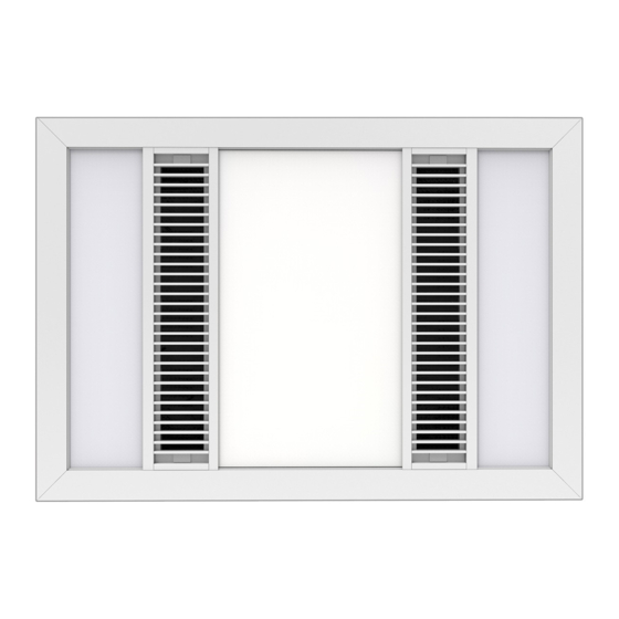
Please use this card as hole cutting template 455mm x 305mm.
Glass shield
Screw behind rubber
Air inlet grille
Terminal
Blocks
Advertisement
Table of Contents

Related Manuals for Manrose FAN6577


Summary of Contents for Manrose FAN6577
- Page 1 20mm. If the room is experience and knowledge, unless they have been given supervision or airtight, the fan will function poorly. MANROSE FAN6577 instruction concerning use of the appliance by a person responsible for 4. Prepare the ceiling their safety.
- Page 2 Socket PLEASE NOTE: Operation unit 1 piece bathroom heater The Manrose Halogen Heater Fan Light has a Triple Thermal Protection 1000W Halogen Heat Lamp (LHT0326) 1 piece System: The Heater FL is equipped with automatic resettable thermal Reflector ceiling joist 220mm switches.
Need help?
Do you have a question about the FAN6577 and is the answer not in the manual?
Questions and answers