Table of Contents
Advertisement
Quick Links
Advertisement
Table of Contents

Related Manuals for Manrose MRHT3


Summary of Contents for Manrose MRHT3
- Page 1 3 Room Kit Installation Instructions Firmware Version 2.0...
-
Page 2: Table Of Contents
Heat Transfer 3 Room Kit Firmware Version 2.0 Contents Definitions/Warning/Caution ......................4 Heat Transfer Systems ......................... 5 Summer Vent Kit ......................... 5 Kit Contents and Accessories ....................... 5 Installation Preparation ........................... 6 Ducting ..........................6 Diffusers ..........................6 Fans ............................. 7 Inlet Grilles .......................... -
Page 3: Definitions/Warning/Caution
Definitions Before use please read and understand these defi nitions. WARNING and/or the use of the symbol refers to conditions where the possibility of injury, or death, exists if the procedure is not followed. CAUTION CAUTION indicates the possibility of damage to the equipment, installation or premises if a procedure is not followed. -
Page 4: Heat Transfer Systems
Give the system time to create warm air circulation through the house. This may take several hours to establish! Kit Contents 3 ROOM KIT MRHT3 Touch Screen Controller - V2.0 Three Speed Mixed Flow Fan Flush Box 150mm x 3m Insulated Ducting... -
Page 5: Installation Preparation
Installation Preparation Plan the installation beforehand to ensure that the best possible ventilation solution is achieved. Lay out fans, intake grilles, branches and ducts in the roof cavity making sure that suitable suspension points for the fans and intake grilles are available. Ducting - Make sure there is at least 2m of duct between the fan and the first bend or branch of which the first metre from the fan must be straight. -
Page 6: Fans
- Suspend fans more than 4m away, from bedrooms, where possible. This will ensure the quietest operation possible and eliminate any resonance. - Find the best mounting place in the roof cavity near to the Manrose touch screen controller location. - Ensure the correct airflow direction is maintained when mounting the fan. -
Page 7: Touch Screen Controller
Installation Touch Screen Controller - Install on an inside wall at eye level in the heat source room, preferably opposite the heat source, where the air temperature can be sensed as accurately as possible and not be adversely affected by direct solar radiation or convection currents. -
Page 8: Home Screen Icons
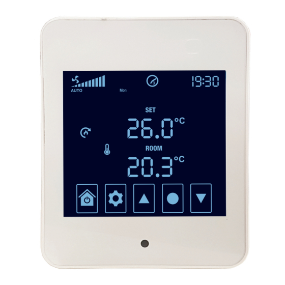
Home Screen Icons System Fan Speed Heat Transfer Mode Heat Transfer ON Temperature Sensing ON Home and Power Settings Select Down Set Temperature Current Room Temperature Key Lock ON Alert Heat Transfer mode selections are AUTO or MAN (manual) 2) When an electronic fault in the system occurs, the alert icon will appear Time and the applicable error code(s) will be displayed instead of the time Scheduler Period and Day... -
Page 9: System Time-Date Settings
System Time-Date Settings ystem Time-Date Settings must be entered before Scheduler start times for HEAT TRANSFER can be set. - On the Home Screen, press SETTINGS for 3 seconds to enter Time-Date Settings and follow the guide below to complete NOTE: Settings shown are examples only - Press HOME at any stage to exit and enter Scheduler Settings... -
Page 10: Commissioning And Testing Inspection Checklist
Commissioning and Testing Inspection Checklist Controller is displaying temperatures correctly. Controller is configured to match the number of speeds the fan motor has. Fan operates on all speeds. Put fan onto high speed to continue inspection. There are no leaks in the ducting. Diffusers are open and not whistling. -
Page 11: Advanced Settings
Advanced Settings Advanced Setting Selection All Manrose Heat Transfer system settings can be changed at any time using the guide below. This guide must also be used to enter the password at setting 018 before settings 019 and above can be changed. -
Page 12: Advanced Settings Menu
Advanced Setting Menu SETTING DESCRIPTION RANGE DEFAULT NOTE Hardware Version Number Firmware Version Number Temperature - Room -9°C - 9°C -1.5°C Reserved Screen Brightness - Maximum 0 - 100% Screen Brightness - Minimum 0 - 100% Boost Time 0 min – 60 min 20 min Reserved Reserved... -
Page 13: Troubleshooting
Troubleshooting An ALERT icon and error code will appear on the Home Screen when there is an electronic fault in the system. If there are multiple faults the error codes will cycle to the next code periodically. Contact Ventair, +61 3 9775 0556, for assistance. Technical Specifications TOUCH SCREEN CONTROLLER V2.0 Temperature Range... - Page 15 Ventair Pty Ltd 4 Capital Place, Carrum Downs VIC 3201 Australia p: +61 3 9775 0556 | e: info@ventair.com.au | w: www.ventair.com.au PUB1672 2102...
Need help?
Do you have a question about the MRHT3 and is the answer not in the manual?
Questions and answers