Table of Contents
Advertisement
Advertisement
Table of Contents

Related Manuals for Echo WT-1610


Summary of Contents for Echo WT-1610
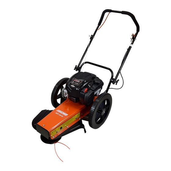
- Page 1 OPERATOR’S MANUAL WHEEL TRIMMER WT-1610 WARNING Read and understand all provided literature before use. Failure to do so could result in serious injury. WARNING Cancer and Reproductive Harm www.P65Warnings.ca.gov 99922205555 www.echo-usa.com © 06/2020 ECHO Incorporated...
- Page 2 Register your ECHO equipment on-line at www.echo-usa.com or by filling out the product registration sheet included in this manual. Registering your product confirms warranty coverage and provides a direct link to ECHO if we find it necessary to contact you.
- Page 3 ECHO brand rental of a like product during the time warranty service is outdoor product.
-
Page 4: Table Of Contents
TABLE OF CONTENTS SAFETY ................................... 1 1.1 SAFETY ALERT SYMBOL ..............................1 1.2 FIRE HAZARD INFORMATION ............................1 1.3 BEFORE OPERATING ................................1 1.4 OPERATION SAFETY ................................2 1.5 MAINTENANCE/STORAGE SAFETY ..........................2 1.6 SAFETY DECAL LOCATIONS ............................. 3 ASSEMBLY................................4 2.1 ADJUST THE HANDLE BAR .............................. -
Page 5: Safety
SAFETY Section The engine on your power equipment, like most outdoor 1.1 SAFETY ALERT SYMBOL power equipment, is an internal combustion engine that burns gasoline or diesel fuel (hydrocarbons). If operating your power equipment in affected areas, it must be equipped with a spark arrestor in continuous effective working order. -
Page 6: Operation Safety
SAFETY 6. Do not operate this machine if you 1.4 OPERATION SAFETY are under the influence of alcohol, medications, substances that 1. Keep hands and feet out of cutting area while machine can affect your vision, balance or is operating to avoid serious personal injury. Stop and judgement. -
Page 7: Safety Decal Locations
SAFETY 1.6 SAFETY DECAL LOCATIONS Familiarize yourself with all of the safety and operational decals on the machine and the associated hazards. See the engine owner’s manual or contact the engine manufacturer for engine safety instructions and decals. Make certain that all safety and operating decals on this machine are kept clean and in good condition. -
Page 8: Assembly
ASSEMBLY Section 2.1 ADJUST THE HANDLE BAR 2.3 FILL THE FUEL TANK 1. Open shipping box and remove packing material. WARNING 2. Loosen T-handles on handle bar. Raise upper portion of handle bar to desired position. Tighten T-handles. Gasoline and diesel fuels are highly 3. -
Page 9: Adjust The Balance
ASSEMBLY 2.4 ADJUST THE BALANCE The balance point of the trimmer can be adjusted by moving the location of the wheels. Adjusting the balance point changes how much force is required at the handle bar to raise the mow ball off the ground. There are two sets of holes in the axle plate for mounting the wheels. -
Page 10: Features & Controls
FEATURES & CONTROLS Section Understanding how your machine works will help you achieve the best results when using your trimmer. The following descriptions define the features and controls of your machine. REFER TO ENGINE OWNER’S MANUAL FOR FURTHER ENGINE OPERATING INSTRUCTIONS. 1. -
Page 11: Operation
OPERATION Section As with any other piece of outdoor power equipment, 4.2 STOPPING THE TRIMMER getting the feel for how your machine operates and getting to know the best techniques for particular jobs are important to overall good performance. Release the trimmer bail. TRIMMING OPERATION 4.3 TRIMMING GUIDE The trimming operation takes place under the body of the... -
Page 12: Parallel Trimming For Push Trimmers
OPERATION 4.4 PARALLEL TRIMMING FOR PUSH TRIMMERS The Wheeled Trimmer can be adjusted to mow with an offset. This allows the machine to trim in hard to reach places. Parallel trimming is adjustable on this model to the left 2". The trimmer body pivots on the axle. To adjust the parallel trimming setting: 1. -
Page 13: Service & Maintenance
SERVICE & MAINTENANCE Section 5.1 MAINTENANCE SCHEDULE The items listed in this service and maintenance schedule are to be checked, and if necessary, corrective action taken. This schedule is designed for units operating under normal conditions. If the unit is operating in adverse or severe conditions, it may be necessary for the items to be checked and serviced more frequently. -
Page 14: Cutting Height Adjustment
SERVICE & MAINTENANCE WARNING BEFORE INSPECTING OR SERVICING ANY PART OF THIS MACHINE, SHUT OFF POWER SOURCE, DISCONNECT SPARK PLUG WIRE FROM SPARK PLUG AND MAKE SURE ALL MOVING PARTS HAVE COME TO A COMPLETE STOP. 5.3 CUTTING HEIGHT ADJUSTMENT The standard cutting height is 2-3/4 inches. -
Page 15: Drive Belt Checking, Tensioning, And Replacement
SERVICE & MAINTENANCE WARNING BEFORE INSPECTING OR SERVICING ANY PART OF THIS MACHINE, SHUT OFF POWER SOURCE, DISCONNECT SPARK PLUG WIRE FROM SPARK PLUG AND MAKE SURE ALL MOVING PARTS HAVE COME TO A COMPLETE STOP. 5.5 DRIVE BELT CHECKING, TENSIONING, AND REPLACEMENT Check the condition of the drive belt annually or after 20 7. -
Page 16: Troubleshooting
Before performing any of the corrections in this troubleshooting chart, refer to the appropriate information contained in this manual for the correct safety precautions and operating or maintenance procedures. Contact your dealer or ECHO for service problems with the machine. -
Page 17: Specifications
SPECIFICATIONS Section DESCRIPTION ENGLISH METRIC Engine Briggs & Stratton 675 EXi Series 163cc ® Drive Push Fuel capacity 0.8 quarts (0.2 gallon) Start Recoil Cutting width 24" 61 cm Cutting height 1-7/8" and 2-3/4" 4.8 cm and 7 cm Nylon cutting string 20"... -
Page 18: Bolt Torque
SPECIFICATIONS 7.1 BOLT TORQUE The tables below are for reference purposes only and their use by anyone is entirely voluntary, unless otherwise noted. Reliance on their content for any purpose is at the sole risk of that person and any loss or damage resulting from the use of this information is the responsibility of that person. -
Page 19: Options
OPTIONS Section PART NUMBER DESCRIPTION 102225155 STRING, .155 DIA, CROSS-FIRE (50 Count / 21” Strips) ® 311155066 STRING, .155 DIA, CROSS-FIRE (1 LB. DONUT) 314155056 STRING, .155 DIA, CROSS-FIRE (3 LB. SPOOL) 102225175 STRING, .175 DIA, CROSS-FIRE (50 Count /21” Strips) 311175067 STRING, .175 DIA, CROSS-FIRE (1 LB. -
Page 20: Product Registration
It’s FAST and EASY! NOTE: your information will never be sold or misused by ECHO, Inc. Registering your purchase enables us to contact you in the unlikely event of a service update or product recall, and verifies your ownership for warranty consideration. - Page 21 WHEELED TRIMMER...
- Page 24 ECHO INCORPORATED 400 Oakwood Road Lake Zurich, IL 60047 www.echo-usa.com Serial Range: 100WTB000001 - 100WTB999999 78796-00...
Need help?
Do you have a question about the WT-1610 and is the answer not in the manual?
Questions and answers