Atari 2600 Installation Manual
4 switch video mod
Hide thumbs
Also See for 2600:
- Field service manual (157 pages) ,
- Owner's manual (52 pages) ,
- Quick start manual (20 pages)
Advertisement
Quick Links
Atari 2600 4 switch Video Mod
Installation Guide
The installation kit contains the following items:
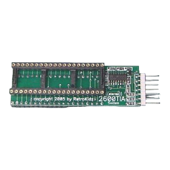
1. Atari 2600 4 switch Mod board
2. Black 3.5mm panel mount jack with attached wires & pins.
3. Black Svideo mini-din panel mount jack with attached wires & pins.
4. Yellow RCA jack with 1 attached wire & pin.
**NOTE** you will need to provide all external cables.
1. AUDIO 3.5mm male plug on one end and two RCA plugs on the other.
2. SVIDEO male-male Svideo cable to connect to your monitor or TV.
3. COMPOSITE If you also want to connect Composite Video you need a
male-male RCA extension cable.
Advertisement

Subscribe to Our Youtube Channel
Related Manuals for Atari 2600


Summary of Contents for Atari 2600
- Page 1 Atari 2600 4 switch Video Mod Installation Guide The installation kit contains the following items: 1. Atari 2600 4 switch Mod board 2. Black 3.5mm panel mount jack with attached wires & pins. 3. Black Svideo mini-din panel mount jack with attached wires & pins.
- Page 2 The following list of tools are also recommended: 1. Phillips & Flat blade screwdrivers 2. Needle nose pliers 3. Sharp angled cutters 4. Hand drill 5. 1/8” and ¼” bits 6. ½” hole cutting bit 7. Awl or scribe 8. Xacto knife 9.
- Page 3 Place 2600 upside down on clean non-scratch surface and remove four screws with the Phillips screwdriver. Two are located along the bottom front of the 2600, the other two are located about ¾ towards the back as shown below. When removing the rear screws make sure to angle your screwdriver as shown below.
- Page 4 Flip the case bottom over & behind the top section to allow access to the motherboard.
- Page 5 Lift motherboard/shield assembly out of case and set the case top and bottom to the side. The motherboard/shield assembly should look similar to the one shown below. Remove the RF cable plug from its mating connector as shown. It is a good idea at this point to completely remove the RF cable from the case bottom as you probably will never use it again.
- Page 6 There are 4 tabs located around the metal shield which need to be straightened with the needle nose pliers as shown below.
- Page 7 If all tabs have been straightened properly you should be able to remove both the top and bottom sections as shown below. Set aside. Phase2 Motherboard Modification Place motherboard so that the TIA chip is in front of you as shown below. Gently with a flat blade screwdriver pry up one side of the chip then the other side until you can remove it with your fingers.
- Page 8 Once the chip is removed place it back into the mod board, making sure that the notch or dot is facing to the left of the board exactly the same as when you removed it from the motherboard.
- Page 9 Now plug the mod board back into the motherboard as shown below making sure to use enough downward pressure to seat the pins in the board into the socket. Visually verify that the board is seated and that you haven’t gotten the pins skewed. Set the motherboard assembly aside for now.
- Page 10 Using the Awl or scribe mark the second hole for the 3.5mm audio jack as shown below.
- Page 11 Using the Awl or scribe mark the third hole for the composite RCA jack as shown below.
- Page 12 Remove motherboard and set aside, now using the 1/8” bit drill 3 pilot holes as shown below.
- Page 13 Using the 1/4” bit enlarge the 3 holes as shown below.
- Page 14 Now, using the ½” hole cutter bit drill the left most hole. Drill at medium speed as shown below.
- Page 15 Turn the cover over and clean the hole of any plastic pieces still clonging to the cover as shown.
- Page 16 Place the mini-din connector in the ½” hole and using the Awl or scribe mark the locations of the 2 mounting holes as shown below.
- Page 17 Now drill the mounting holes with the 1/8” bit as shown below.
- Page 18 Counter sink the 2 mounting holes by angling the X-acto knife as shown below.
- Page 19 Turn the cover over and check the 3.5mm audio jack to see if the hole is large enough for threads to go through the cover as shown .
- Page 20 If the hole is not large enough then you can use the X-acto knife to enlarge the hole as necessary. Now counter sink this hole from the inside of the case as shown below. This is necessary due to the thickness of the plastic cover. Otherwise the threads of the jack would not be long enough to attach the nut.
- Page 21 Next verify the proper hole size of the RCA jack as shown below. Enlarge as necessary with the X-acto knife.
- Page 22 Insert the 3.5mm jack and tighten nut with pliers as shown below.
- Page 23 Next insert the metal washer through the yellow wire, then the ring terminal, and last the nut as shown below.
- Page 24 Tighten nut with pliars. Now flip case over insert the mini-din jack from the inside of the cover and hold with one hand while inserting the 2 mounting screws. Tighten with screwdriver as shown below.
- Page 25 Insert pin& yellow wire from RCA jack into the blank empty slot of the white connector shell beside the existing yellow wire as shown below.
- Page 26 Plug connector into the mod board as shown below. If you have one available you can also use a nylon tie to keep the wires tidy.
- Page 27 Flip the motherboard over and insert at an angle into the top cover like the picture below. This may take some effort to do as the switches on the motherboard are long and may need to be pushed into their respective holes. However do not use too much force as you will break or damage them...
- Page 28 Place bottom cover back making sure that it is positioned correctly.
- Page 29 Replace the two BACK screws first then the two front ones as shown below.
- Page 30 The back of your 2600 should look similar to below.
- Page 31 YOUR DONE!! NOW YOU CAN ENJOY ALL YOUR VINTAGE ATARI 2600 GAMES WITH CRISP CLEAN VIDEO!!!!!
Need help?
Do you have a question about the 2600 and is the answer not in the manual?
Questions and answers