Table of Contents
Advertisement
Quick Links
Advertisement
Table of Contents

Related Manuals for ADC HMS-317


Summary of Contents for ADC HMS-317
- Page 1 NSTALLATION UIDE HMS-318 HMS-317 HMS-317 HMS-318 ANAGEMENT HELF Model/List Part Number CLEI 150-1128-02 T1MFUR04 HMS-317 List 2 150-1128-03 T1MF1R04 HMS-317 List 3 150-1129-02 T1MFVS04 HMS-318 List 2 150-1129-22 HMS-318 List 2B...
- Page 2 Contents herein are current as of the date of publication. ADC reserves the right to change the contents without prior notice. In no event shall ADC be liable for any damages resulting from loss of data, loss of use, or loss of profits, and ADC further disclaims any and all liability for indirect, incidental, special, consequential or other similar damages.
- Page 3 Unpack each container and inspect the contents for signs of damage. If the equipment has been damaged in transit, immediately report the extent of damage to the transportation company and to ADC DSL Systems, Inc. Order replacement equipment, if necessary.
- Page 4 Unpack and Inspect Your Shipment LTPH-UG-1166-01 July 15, 2002 HMS-317 and HMS-318...
-
Page 5: Table Of Contents
Connector P4 (Loop 2) ......................24 Appendix B - Standard PIC Color Code _________________________________________________ 26 Appendix C - Specifications____________________________________________________________ 27 Appendix D - Product Support _________________________________________________________ 28 Appendix E - Abbreviations ___________________________________________________________ 29 Certification and Warranty____________________________________________________________ 31 HMS-317 and HMS-318 July 15, 2002... - Page 6 6. HLU Slot Wire-wrap Pinouts for HDSL2 Circuits ..................7 7. HLU Slot Wire-wrap Pinouts for HDSL4 Circuits ..................8 8. ADC HCP-322 List 1 and List 2 Connector Panel..................9 9. Typical HiGain G.703 Application .......................9 10. HLU Slot Wire-wrap Pinouts for G.703/HDSL Circuits ................10 11.
- Page 7 3. J31/J25 - AUX RS-232 PORT (DTE) ......................14 4. P1-DSX Receive, Tip and Ring........................18 5. P2-DSX Transmit, Tip and Ring .........................20 6. P3-HDSL Loop 1, Tip and Ring........................22 7. P4-HDSL Loop 2, Tip and Ring........................24 8. Standard PIC Color Code ..........................26 HMS-317 and HMS-318 July 15, 2002...
- Page 8 List of Tables LTPH-UG-1166-01 July 15, 2002 HMS-317 and HMS-318...
-
Page 9: Overview
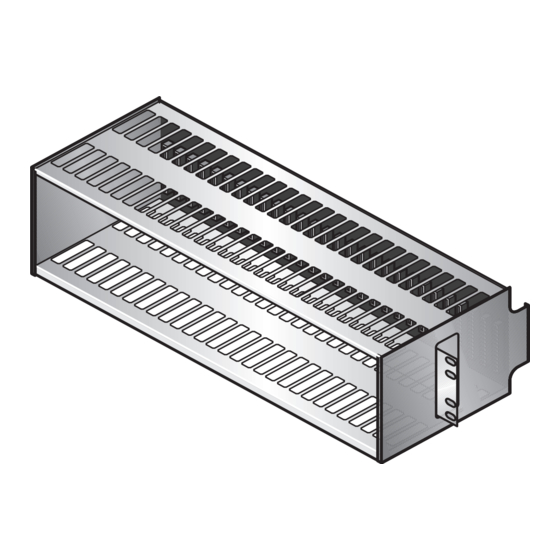
• M5 x 0.8 by 10 mm mounting screws (4) • BNC-T connector 50 W BNC terminator • • HMS-317 and HMS-318 Management Shelf Quick Installation Guide HMS-317 23" (58.42 cm) 5.22" (13.26 cm) HLU1-HLU28 HMS-318 19" (48.26 cm) 5.22"... -
Page 10: Hms-317 And Hms-318 Rear View
LTPH-UG-1166-01 The HMS-317 (List 2 and List 3) shelf has one HMU and 28 HLU card slots. The HMS-318 (List 2 and List 2B) shelf has one HMU and 22 HLU card slots. Communications between the HMU slot and the HLU card slots are routed through the backplane. -
Page 11: Dsx-1 And Hdsl Span Connectors
DSX-1 and HDSL Span Connectors Figure 2 on page 2 shows the location of the HDSL span connectors on the backplane of the HMS-317 and HMS-318 shelves. For information on the signal and pin assignments for these connectors, see “Appendix A - Signal and Pin Assignments”... -
Page 12: Power And Alarm Connections
3) provides a central connection point for the CO primary input power feed. Slots 1 through 14 on the HMS-317 List 2 are powered by the -48VA bus. Slots 15 through 28 are powered by the -48VB bus. The two GND terminals are tied together. The HMU-319 is diode-OR’ed to both power busses, to guard against power failure in the event that one power supply is lost. -
Page 13: Alarms Terminal Block
4) is a 22-pin wire-wrap connector. TB1 provides a central connection point to the Normally Closed (NC), Common (COM) and Normally Open (NO) relay contacts for installing optional alarm inputs connections. CRIT CRIT Figure 4. Alarms Terminal Block (TB2) HMS-317 and HMS-318 July 15, 2002... -
Page 14: Connecting To Hdsl Circuits
This section provides information on making DSX-1 and HDSL connections to HMS-317 and HMS-318 shelves. DSX-1 and HDSL Plug-in Connections DSX-1 connections to the HMS-317 and HMS-318 shelves can be made through HMS backplane connectors P1 (RCV to DSX) and P2 (XMT from DSX). HDSL connections to the shelves can be made through backplane connectors P3 (HDSL Loop 1) and P4 (HDSL Loop 2). -
Page 15: Connecting To Hdsl2 Circuits
This section provides information on making DSX-1 and HDSL2 connections to HMS-317 and HMS-318 shelves. HDSL2 Plug-in Connections DSX-1 connections to the HMS-317 and HMS-318 shelves can be made through HMS backplane connectors P1 (RCV to DSX) and P2 (XMT from DSX). HDSL2 connections to the shelves can be made through backplane connectors P3 (HDSL Loop 1) and P4 (HDSL Loop 2). -
Page 16: Connecting To Hdsl4 Circuits
This section provides information on making DSX-1 and HDSL4 connections to HMS-317 and HMS-318 shelves. HDSL4 Plug-in Connections DSX-1 connections to the HMS-317 and HMS-318 shelves can be made through HMS backplane connectors P1 (RCV to DSX) and P2 (XMT from DSX). HDSL4 connections to the shelves can be made through backplane connectors P3 (HDSL Loop 1) and P4 (HDSL Loop 2). -
Page 17: Connecting G.703 Circuits To The Hms-318
9), can be used to connect up to 22 G.703 circuits to HiGain ELU-319 line units housed in the HMS-318 shelf. The ADC HCP-322 List 1 panel has 44 BNC connectors for connecting G.703 75 W circuits to ELU-319 List 1, List 5 and 5D line units. The ADC HCP-322 List 2 panel contains 22 DB-15 connectors for connecting G.703 120 W circuits to ELU-319 List 6 and 6D line... -
Page 18: G.703 Wire-Wrap Connections
(10 ma maximum, +5 Vdc for HLU-319 List 2D) when activated Fuse alarm is normally floating (0 to -80V maximum) and at -48V (10 ma maximum) when activated Figure 10. HLU Slot Wire-wrap Pinouts for G.703/HDSL Circuits July 15, 2002 HMS-317 and HMS-318... -
Page 19: Hlu Slot Wire-Wrap Pinouts For G.703/Hdsl2 Circuits
Fuse Alarm ** Notes: System alarm and management bus reserved. Fuse alarm normally floating (0 to -80 Vdc maximum) and at -48Vdc (10 ma maximum) when activated. Figure 11. HLU Slot Wire-wrap Pinouts for G.703/HDSL2 Circuits HMS-317 and HMS-318 July 15, 2002... -
Page 20: Hlu Slot Wire-Wrap Pinouts For G.703/Hdsl4 Circuits
Fuse Alarm ** Notes: System alarm and management bus reserved. Fuse alarm normally floating (0 to -80 Vdc maximum) and at -48Vdc (10 ma maximum) when activated. Figure 12. HLU Slot Wire-wrap Pinouts for G.703/HDSL4 Circuits July 15, 2002 HMS-317 and HMS-318... -
Page 21: Asynchronous Management Ports
Overview SYNCHRONOUS ANAGEMENT ORTS Two RS-232 communication ports, J30 and J31 on HMS-317 and J24 and J25 located on the HMS-318 backplane (see Figure 13), provide for optional OS and AUX management interfaces to be connected to the HiGain system. -
Page 22: Multishelf Network Connections
ULTISHELF ETWORK ONNECTIONS The BNC connector (J32 on the HMS-317 and J26 on HMS-318; see Figure 14) can be used to connect the management ports of up to 32 shelves into an integrated network through a 10BASE-2 (IEEE 802.3) Ethernet LAN. -
Page 23: Power Dissipation Factors
OWER ISSIPATION ACTORS The HMS-317 and the HMS-318 are both 12-inch (30.48 cm) deep individual CO equipment frames with open-faced mountings and natural convection cooling. GR-63-CORE limits the maximum dissipation of the HMS shelf to 134.7 Watts per square foot. -
Page 24: Installation
Installation LTPH-UG-1166-01 NSTALLATION This section contains site requirements and installation instructions for the HMS-317 List 2 and List 3, and the HMS-318 List 2 and List 2B. EQUIREMENTS The -48VA and -48VB busses provide the -48V shelf battery feed. Each bus should be fused at 10 Amperes. -
Page 25: Input Power Terminal Strip (Tb1)
Connect the optional alarm outputs to the Alarms Terminal Board (TB2; Figure 17). CRIT CRIT Figure 17. Terminal Strip TB2, HMU-319 Alarm Outputs Install the line units (HLUs) and the HMU-319 management unit in the shelf, as described in the applicable user manual. HMS-317 and HMS-318 July 15, 2002... -
Page 26: Appendix A - Signal And Pin Assignments
Appendix A - Signal and Pin Assignments LTPH-UG-1166-01 A - S PPENDIX IGNAL AND SSIGNMENTS This section provides information on Tip and Ring signal and pin assignments to HMS-317 and HMS-318 management shelves. P1-DSX Receive, Tip and Ring ..................P2-DSX Transmit, Tip and Ring .................. - Page 27 LTPH-UG-1166-01 Appendix A - Signal and Pin Assignments Table 4. P1-DSX Receive, Tip and Ring (Cont.) Cable Pin Number Card Slot Pin Number Slot “B” denotes Tip HMS-317 HMS-318 “2” denotes Ring HMS-317 and HMS-318 July 15, 2002...
-
Page 28: Connector P2 - Dsx Transmit
Appendix A - Signal and Pin Assignments LTPH-UG-1166-01 Connector P2 - DSX Transmit The following table provides signal and pin assignment information for making DSX transmit circuit connections to HMS-317 and HMS-318 shelves. Table 5. P2-DSX Transmit, Tip and Ring Cable Pin Number Card Pin Number Slot “A”... - Page 29 LTPH-UG-1166-01 Appendix A - Signal and Pin Assignments Table 5. P2-DSX Transmit, Tip and Ring (Cont.) Cable Pin Number Card Pin Number Slot “A” denotes Tip HMS-317 HMS-318 “1” denotes Ring HMS-317 and HMS-318 July 15, 2002...
-
Page 30: Connector P3 (Loop 1)
Connector P3 (Loop 1) Table 6 provides connector P3 signal and pin assignment information for making HDSL, HDSL2 and HDSL4 connections to HMS-317 and HMS-318 shelves. Table 6. P3-HDSL Loop 1, Tip and Ring Cable Pin Number Card Pin Number “F”... - Page 31 LTPH-UG-1166-01 Appendix A - Signal and Pin Assignments Table 6. P3-HDSL Loop 1, Tip and Ring (Cont.) Cable Pin Number Card Pin Number “F” denotes Tip HMS-317 HMS-318 Slot “6” denotes Ring HMS-317 and HMS-318 July 15, 2002...
-
Page 32: Connector P4 (Loop 2)
Connector P4 (Loop 2) Table 7 provides connector P4 signal and pin assignment information for making HDSL, HDSL2 and HDSL4 connections to HMS-317 and HMS-318 shelves. Table 7. P4-HDSL Loop 2, Tip and Ring Cable Pin Number Card Pin Number Slot “K”... - Page 33 LTPH-UG-1166-01 Appendix A - Signal and Pin Assignments Table 7. P4-HDSL Loop 2, Tip and Ring (Cont.) Cable Pin Number Card Pin Number Slot “K” denotes Tip HMS-317 HMS-318 “9” denotes Ring HMS-317 and HMS-318 July 15, 2002...
-
Page 34: Appendix B - Standard Pic Color Code
Black Orange Black Green Black Brown Black Slate Yellow Blue Yellow Orange Yellow Green Yellow Brown Yellow Slate Violet Blue Violet Orange Violet Green Violet Brown Violet Slate White Blue White Orange White Green July 15, 2002 HMS-317 and HMS-318... -
Page 35: Appendixc - Specifications
5.33 in. (13.26 cm) HMS-317: 23 in. (58.4 cm) Width HMS-318: 19 in. (48.06 cm) HMS-317: 11.5 in. (30 cm) Depth HMS-318: 11.5 in. (30 cm) HMS-317: 11.6 lb (5.36 kg) Weight HMS-318: 9.7 lb (4.4 kg) HMS-317 and HMS-318 July 15, 2002... -
Page 36: Appendix D - Product Support
UPPORT ADC Customer Service Group provides expert pre-sales and post-sales support and training for all its products. Technical support is available 24 hours a day, 7 days a week by contacting the ADC Technical Assistance Center (TAC). • Quotation Proposals Sales Assistance •... -
Page 37: Appendixe - Abbreviations
HiGain Management Unit HiGain Remote Enclosure HiGain Remote Unit Light Emitting Diode NLOC Network Local Loopback NVRAM Non-volatile Random Access Memory Plastic Insulated Conductor Receive Return Material Authorization Synchronous Transport System Transmit ZBTS Zero Byte Timeslot HMS-317 and HMS-318 July 15, 2002... - Page 38 Appendix E - Abbreviations LTPH-UG-1166-01 July 15, 2002 HMS-317 and HMS-318...
-
Page 39: Certification And Warranty
ADC’s entire liability for software that does not comply with the foregoing warranty and is reported to ADC during the 90-day warranty period is, at ADC’s option, either (a) return of the price paid or (b) repair or replace of the software. ADC also warrants that, for a period of thirty (30) days from the date of purchase, the media on which software is stored will be free from material defects under normal use. - Page 40 ADC DSL Systems, Inc. 14402 Franklin Avenue Tustin, CA 92780-7013 Tel: 714.832.9922 Fax: 714.832.9924 Technical Assistance Tel: 800.638.0031 Tel: 714.730.3222 Fax: 714.730.2400 : LTPH-UG-1166-01, I OCUMENT SSUE ISO 9001/TL 9000 ´,FP¶67¨ 1238486 DNV Certification, Inc. REGISTERED FIRM...
Need help?
Do you have a question about the HMS-317 and is the answer not in the manual?
Questions and answers