
Subscribe to Our Youtube Channel
Related Manuals for TMS ST Series


Summary of Contents for TMS ST Series
- Page 1 ST-1000-D1 LIGHTING CONTROLLER UNIT ST Series Lighting Controller ST-1000-D1 (CONSTANT AND TRIGGER MODE) USER MANUAL Rev 1.0 20 OCT 2016...
-
Page 2: Table Of Contents
ST-1000-D1 LIGHTING CONTROLLER UNIT Contents Introduction .............................. 1 Features List ............................1 Applications ............................1 Hardware ..............................2 Packing List ............................2 Front Panel ............................2 Configuration ............................3 Connections ............................3 Current DIP Switch Settings ......................... 5 Power ON ............................. 6 Operation Mode ............................ -
Page 3: Introduction
ST-1000-D1 LIGHTING CONTROLLER UNIT Introduction Features List 1 channel lighting controller card with VR and Selection Switch Voltage control for channel up to 24V DC Lighting output voltage 24VDC Current Selection 200mA, 400mA, 700mA, 700mA and up to 2A ... -
Page 4: Hardware
ST-1000-D1 LIGHTING CONTROLLER UNIT Hardware Packing List Please make sure that the following parts are in the packing list: ST-1000-D1 lighting controller unit Adaptor +24V with Power Cord 110 - 240 (Optional) LED Lightings (Optional) Ext. Lighting Cable (Optional) ... -
Page 5: Configuration
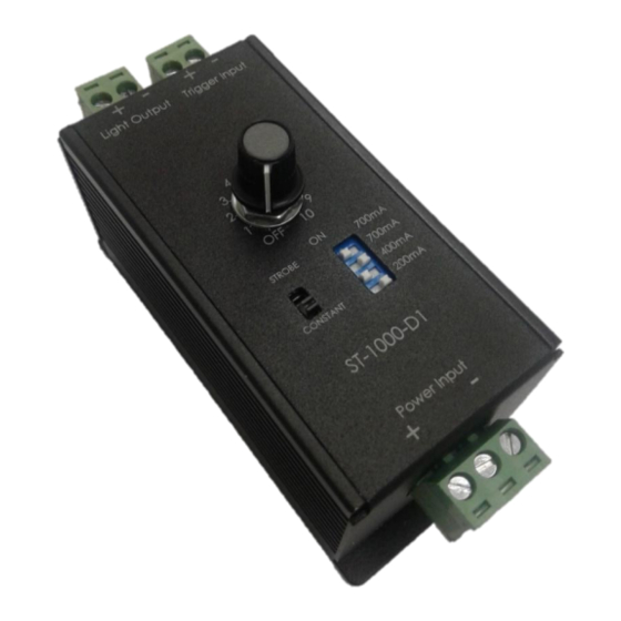
ST-1000-D1 LIGHTING CONTROLLER UNIT Configuration Connections For ST-1000-D1 to operate properly, the unit terminals must be connected correctly. The terminals voltage polarity must be followed accordingly to prevent damage to the unit. Board Power Terminals These terminals are to be connected to a 24V DC power supply with minimum 500mA capability. - Page 6 ST-1000-D1 LIGHTING CONTROLLER UNIT TOP VIEW VR KNOB Control LED Intensity Constant and Trigger Select Switch At Top View, the ST Control card, all the Positive terminals are with ‘+’ label and the Negative terminals are with ‘-’ label, as shown in the above photo.
-
Page 7: Current Dip Switch Settings
ST-1000-D1 LIGHTING CONTROLLER UNIT Current DIP Switch Settings Switches is located at the lower right of the controller as shown in the photo below. Switches sets the maximum output current to the Lighting Output for over current protection. Factory default setting is 700mA. Caution: Make sure the selected maximum current output is suitable for the lightings to prevent damage to both the lightings and the ST lighting controller unit. -
Page 8: Power On
ST-1000-D1 LIGHTING CONTROLLER UNIT Power ON The default current setting for the ST controller is 700mA. If other current settings are desired, please refer to the previous section before power on the unit. Connect the lighting connectors to the lighting connection terminals. Connect a voltage supply from 24V DC to the Board Power Terminals. -
Page 9: St-1000-D1 Specification
ST-1000-D1 LIGHTING CONTROLLER UNIT Pull High / Pull Low ST-1000-D1 Specification CONTROL: Manual Control (Adjustable) General: Dimension 78mm x 40.50 x 53.4mm Power Input +24 VDC Board Max Power Consumption 50mA±10% @ 24V Board Voltage 24 VDC Channels: 1 Channels Channel Control Independent Output Mode... -
Page 10: Dimension Layout
ST-1000-D1 LIGHTING CONTROLLER UNIT Dimension Layout Simple Connection ST-1000-D1 - 8 -... -
Page 11: Cable Information
ST-1000-D1 LIGHTING CONTROLLER UNIT Cable Information i) EXT-24V-F-3M Extension Cable of 3 Meter with SM connector ii) EXT-24V-F-3M-TB Extension Cable of 3 Meter with Terminal Block connector - 9 -... -
Page 12: Power Cord Information
ST-1000-D1 LIGHTING CONTROLLER UNIT Power Cord Information The cable length is 1.8 Meter length of power cord. 240VAC Power Cord (UK) 220VAC Power Cord (EU) 110VAC Power Cord (US) - 10 -... -
Page 13: Lighting Connector Of Sm
ST-1000-D1 LIGHTING CONTROLLER UNIT Lighting Connector of SM Pin 1 -- Red wire (+ve) Pin 3 -- White wire (-ve) - 11 -... - Page 14 Thank you for downloading this document from www.machine-vision-shop.com If you have any questions, you need help composing the right package for your application or do you want to order? Natascha Overhof Feel free to contact us via e-mail at sales@vision- consultancy.nl or visit our webshop.
Need help?
Do you have a question about the ST Series and is the answer not in the manual?
Questions and answers