Table of Contents
Advertisement
Quick Links
Espert 500
OPERATION MANUAL
Thank you for purchasing Espert 500. This is a high-precision, extremely high speed micromotor rotary hand tool system.
This system is designed for high-precision, small diameter deburring, grinding and a wide variety of other applications.
Keep this Operation Manual near Espert 500 system for any operators to refer to whenever operating this system.
Please read this Operation Manual carefully prior to use.
1. CAUTIONS FOR HANDLING AND OPERATION
Read these cautions carefully and only use in the manner intended.
Safety instructions are intended to avoid potential hazards that could result in personal injury or damage to
the device. Safety instructions are classified as follows in accordance with the seriousness of the risk.
Class
A hazard that could result in bodily injury or damage to the device if the safety instructions are not
WARNING
followed.
A hazard that could result in light or moderate bodily injury or damage to the device if the safety
CAUTION
instructions are not followed.
N O T I C E
General information needed to operate the device safely.
A. GROUNDING INSTRUCTIONS
1. In the event of a malfunction or breakdown, grounding provides a path of least resistance for electric current to reduce the risk of
electric shock. This tool is equipped with an electric cord having an equipment-grounding conductor and a grounding plug. The plug
must be plugged into a matching outlet that is properly installed and grounded in accordance with all local codes and ordinances.
2. Do not modify the plug provided - if it will not fit the outlet, have the proper outlet installed by a qualified electrician.
3. Improper connection of the equipment-grounding conductor can result in a risk of electric shock. The conductor with insulation having
an outer surface that is green with or without yellow stripes is the equipment-grounding conductor. If repair or replacement of the
electric cord or plug is necessary, do not connect the equipment-grounding conductor to a live terminal.
4. Check with a qualified electrician or service personnel if the grounding instructions are not completely understood, or if in doubt as to
whether the tool is properly grounded.
5. Use only 3-wire extension cords that have 3-prong grounding plugs and 3-pole receptacles that accept the tool's plug.
6. (120V) This tool is intended for use on a circuit that has an outlet that looks like the one illustrated in Sketch A in Figure (below).
The tool has a grounding plug that looks like the plug illustrated in Sketch A in figure (below). A temporary adapter, which looks like the
adapter illustrated in Sketches B and C, may be used to connect this plug to a 2-pole receptacle as shown in Sketch B if a properly
grounded outlet is not available. The
temporary adapter should be used
only until a properly grounded outlet
can be installed by a qualified
electrician. The green-colored rigid
ear, plug, and the like, extending
from the adapter must be connected
to a permanent ground such as a
GROUNDING
properly grounded outlet box.
PIN
Note : Adopter (Figure B) not for use in
Canada.
7. USE PROPER EXTENSION CORD. Make
sure your extension cord is in good
Ampere Rating
condition. When using an extension cord,
be sure to use one heavy enough to carry
More
the current your product will draw. An
Than
undersized cord will cause a drop in line
0
voltage resulting in loss of power and
6
overheating. Table (below) shows the
10
correct size to use depending on cord length
12
and nameplate ampere rating. If in doubt,
Only the applicable parts ot the Table need to be included. For instance, a 120volt product
use the next heavier gauge. The smaller
need include the 240-volt heading.
the gauge number, the heavier the cord.
B. OTHER WARNING INSTRUCTIONS
1. Do not exceed the " Maximum Allowable Motor Rotation Speed " (Refer to " 15. SPECIFICATIONS ").
2. When sensing that the attachment and motor are overheated during operation, reduce the working force or the motor rotation speed,
or stop the operation until the attachment cools down before restarting.
3. Always wear cap, gloves, Iong sleeve shirt, safety glasses and hearing protection anytime this device is in use.
4. Do Not Touch the attachment or motor when the system is operating.
5. This is a high torque system and burs can grab on the workpiece. Always wear gloves to prevent injury anytime you are using this
system. Grinding and deburring produces lots of chips and other dust, keep work are clean and put away items that can be damaged
by chips, sand or other contaminants.
6. Check that the collet has been securely tightened prior to each use. Burs can fly loose from the collet and injure operator or anyone nearby.
7. Avoid applying heavy hand pressure during operation; Iet the tool do the work. Heavy force can bend or break bur shanks which can
injure operator or anyone nearby. If the motor slows down noticeably during operation, you are applying too much pressure; this type
of operation will shorten motor, attachment and tool life and dramatically reduce productivity.
8. Do not use bent, broken, cracked or damaged tools, or tools with excessive runout. When using tools with a very large head to shank
diameter ratio sudden speed increases can bend or break shank. When using a new or large tool, rotate it at low speed and increase
speed gradually for safety.
9. Always operate tools within the tool manufacturer's recommended speed limits. Use of a tool outside of the manufacturer's
recommended speed limits could cause damage to the spindle and injury to the operator. A Foot Pedal can be used to vary speed.
10. Do not hit or drop the attachment or motor because the shock can damage internal components. Always set the CONTROLLER on a
flat, hard, steady surface.
11. If the CONTROLLER, motor or attachment emit smoke, burning plastic odor or any other unusual odor, please immediately turn off
the power switch, disconnect the power cord and send to NAKANISHI for service.
12. Never attempt to operate this system, touch power cord or switch unit on or off, etc. with wet hands. Failure to adhere to this warning
can result in severe electric shock.
13. Do not exceed 13mm overhang for mounted grindstones. In case overhang must exceed 13mm reduce the motor speed in
accordance with Table 1 .
Table 1. Overhang versus Speed
Overhang (mm)
Maximum Operating Speed (rpm)
20
N x 0.5
25
N x 0.3
50
N x 0.1
N : Max. operating speed at 13mm overhang.
C. CAUTION
1. This system can operate in temperatures from 0°C to 40°C. If condensation forms on the unit please do not operate the system
it can short out and there is danger of electric shock.
2. This system is not approved for use in flammable or explosive environments or with flammable or explosive materials.
3. Never oil the bearings. This attachment is assembled with permanently greased bearings.
4. Please check the motor and handpiece prior to each use for vibration, abnormal noises, heat, and rough or stiff rotation. If any
of the above conditions are beyond acceptable limits, please send the system to NAKANISHI for service.
5. Never move the Chuck Control Ring to Open while the motor is running, the motor and attachment will be damaged. Only
change tool with the motor completely stopped.
6. When using large cutting tools, tools with a head diameter larger than 4mm rotate the motor and attachment at slow speed. It is
very easy to bend and break large cutting tools at high rotation speeds.
7. If the motor protection circuit repetitively activates and stops the motor, you are using too much force. Please use less hand
force and continue the operation. Heavy handed usage will result in dramatically shortened motor, attachment and tool life.
8. Please clean the collet and spindle center shaft weekly as failure to do this can cause contaminants to build up in the collet and
increase runout or reduce the clamping strength of the collet.
9. Do not disassemble, modify or attempt to repair the CONTROLLER, Motor Attachment and Foot Pedal as it will damage internal
components. There are no user serviceable parts available.
10. Be careful not to be injured by grinder or cutting tool while working.
11. Verify type and use only properly rated fuse. Refer to the " 10. FUSE REPLACEMENT " section.
12. When cleaning an Attachment, stop the motor, Turn OFF the Main Power Switch and remove debris with a soft brush or a cloth.
Do not blow air into the Attachment with compressed air as foreign particles or cutting debris may get into the ball bearing.
13. Max. input voltage fluctuations : +/-10%
14. Pollution degree 2
15. Overvoltage category II
16. Max. Operating altitude : 2000m
17. Operating humidity range : 10 - 85% RH
18. Indoor use
19. Place equipment so that power supply cord can be quickly pulled out of inlet in case of emergency.
20. Disconnect from power before doing maintenance on handpieces.
D. NOTICE
1. Do not tighten the collet without mounting a cutting tool or dummy bur as this will result in damage to the collet and spindle.
2. Always insert the bur fully into the collet even when not in use.
3. Don't use pencils, pens or other sharp objects on the Front Panel buttons.
4. Turn OFF the power after rotation has completely stopped.
5. User is solely responsible for maintaining control of operation, maintenance and periodic inspection of the system.
6. Only use grounded power sources. Using a non-specified Power Cord, the risk of fire by over-heat of the cord is possible. In case
of damage to the CONTROLLER, return to NAKANISHI dealer service.
7. Service and repair must be performed by NSK NAKANISHI or an authorized service center. Return to NSK NAKANISHI or an
authorized service center.
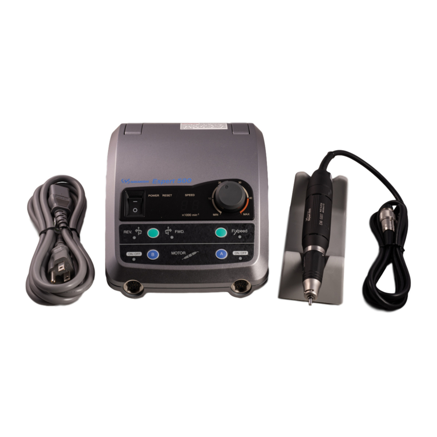
2. PARTS NAMES
[6]
[8]
[1]
[7]
[5]
[4]
[11]
[14]
[16]
[1] CONTROLLER
[2] Motor Handpiece
[3] NAKANISHI Smart Switch
[4] Optional Foot Pedal
[5] Power Switch
[6] Power Lamp
[17]
[17]
[18]
[18]
[19]
[19]
[7] Reset Lamp
Fig.2
Degree of Risk
Grounding Method
ADAPTER
METAL SCREW
GROUNDING
COVER OF GROUND
MEANS
GROUNDING
OUTLET BOX
PIN
Minimum gauge for cord
Volts
Total length of cord
120V
7.5m (25ft.)
15m (50ft.)
30m (100ft.) 45m (150ft.)
240V
15m (50ft.)
30m (100ft).
60m (200ft.) 90m (300ft.)
Not
More
Than
6
18
16
16
10
18
16
14
12
16
16
14
16
14
12
Not Recommended
13
[9]
[2]
[3]
[10]
[12]
[20]
[13]
[15]
Fig.1
[8] Speed Display
[15] Motor A Connector
[9] Speed Control Knob
[16] Motor B Connector
[10] Speed Limit Release Button
[17] Foot Pedal Connector
[11] Forward/Reverse
[18] Power Cord
(FC-40)
Selector Switch
[19] Power Connector Assembly
[12] FiXpeed Switch
[20] Handpiece Stand
[13] Motor A Switch
[14] Motor B Switch
3. SETTING UP THE CONTROLLER
3-1. Connecting the Motor/Attachment
Insert the motor cord plug into the Motor Plug Connector [15] and
OM-K0331E 004
align the pin on the plug with the groove on the connector and
tighten the motor cord plug nut (Fig. 3).
3-2. Connecting the Optional Foot Pedal
Insert the Foot Pedal cord plug into the Foot Pedal Connector
[17] and align the pin on the plug with the groove on the
connector (Fig. 4).
3-3. Connecting the Power Cord
Insert the Power Cord [18] plug into the Power Connector
Assembly [19] on the back of the CONTROLLER securely and
carefully align the pins (Fig. 5).
4. OPERATING PROCEDURES
(1) Connect Power Cord [18] to AC plug.
(2) Make sure the Speed Control Knob [9] is set at the lowest speed position.
(3) Turn Power Switch [5] ON (Green Power Lamp will light)
(4) Select the direction of rotation with the Forward/Reverse Selector Switch [11] . Each time this switch is pressed,
the direction changes.
(5) To switch between motor A and motor B press either A [13] or B [14] to select the respective motor. The lamp on
the CONTROLLER for the selected motor will light. Either push A [13] or B [14] again to start rotation or push the
NAKANISHl Smart Switch on the appropriate motor.
CAUTION
• If the motor lamp is already lit pressing the A [13] or B [14] button will start rotation. Please look carefully
at the CONTROLLER's front panel before pushing the motor select button.
• Motor A and B can not be run simultaneously.
Operation 1
Manual Operation
(6) Set the rotation speed with the Speed Control Knob [9] and check the speed on the Speed Display [8].
(7) Select the desired motor by pressing either Motor Switch A [13] or B [14] .
A [13] = A Motor
After selecting the motor either press the NAKANISHI Smart Switch [3] or press the Motor Switch again.
14
(8) To stop the motor rotation either press Motor Switch A [13] or B [14] or the NAKANISHI Smart Switch again.
12
12
Operation 2
Foot Pedal Operation
(6) Set the maximum rotation speed with the Speed Control Knob [9] and check the speed on the Speed Display [8].
(7) Depress Foot Pedal [4] and the motor will rotate. The rotation speed can be varied up to the preset maximum,
depending on the degree of depression of the Foot Pedal [4].
Auto Speed System
To fix the speed within the range set by the Speed Control Knob [9], with the motor running, depress the Foot Pedal [4]
to the desired speed and press Motor Switch A [13] or B [14], depending on which motor is being used. The lamp on the
CONTROLLER will flash and the rotation speed will be maintained even if the Foot Pedal [4] is released. To cancel the
Auto Speed System press Motor Switch A [13] or B [14], the NAKANISHI Smart Switch [3] or depress the Foot Pedal [4]
again.
5. MEMORY SPEED FUNCTION, FIXPEED
(1) Setting the memory speed function
First with the motor stopped, preset the desired speed on the Speed Control Knob [9]. Next, press the FiXpeed
Switch [12] for more than 1 second. A 'beep' will sound and the FiXpeed lamp will light. The motor is now set to run
at the FiXpeed setting.
To Change FiXpeed Memory
Repeat the above procedure.
NOTICE
FiXpeed memory cannot be set in excess of 30,000 min
(2) Using Memory Speed Function
Select the desired motor by pressing either Motor Switch A [13] or B [14].
A [13] = A Motor
After selecting the motor either press the NAKANISHI Smart Switch [3] or press the Motor Switch again. The
FiXpeed lamp will flash when the motor is running. During Foot Pedal [4] operation the FiXpeed set in memory will
act as the upper limit and the Foot Pedal [4] will still vary speed.
(3) Clearing the FiXpeed Memory
Push and hold the FiXpeed Switch [12], a 'beep' will sound and the FiXpeed lamp will shut off. The FiXpeed
memory is cleared.
(4) To Undo the Clear
Press the FiXpeed Switch [12], the FiXpeed lamp will light. The FiXpeed memory has been restored.
When the Espert 500 system is shipped from the factory, the FiXpeed is preset for both motor A and B to 20,000min
(rpm).
6. SPEED LIMIT
When using small diameter burs the Espert 500 system can be operated at more than 40,000min
Speed Limit Release Button [10] and turn the Speed Control Knob [9] to the desired speed.
CAUTION
Use of more than 40,000 min
acceptable speed in excess of 40,000 min
recommended maximum speed.
7. MOTOR PROTECTION CIRCUIT
When the motor is operated with a load exceeding its limits or the handpiece is locked, the Motor Protection Circuit
operates and interrupts the power supply to the motor. When the Motor Protection Circuit has been triggered the
Reset Lamp [7] Iights and an Error Code appears on the Speed Display [8].
Resetting the Motor Protection Circuit
During manual operation the circuit can be reset by pressing Motor Switch A [13] or B [14] again. During Foot Pedal
operation, release the Foot Pedal [4] completely and the circuit will be reset.
8. POWER UP MEMORY FUNCTION
When the Power Switch [5] is turned On, the rotation direction and Hand/Foot selections being used when the unit
was shut down are restored. Please pay careful attention to the rotation direction.
9. ERROR CODES
When the Motor Protection Circuit stops the motor due to some system failure, such as overload, wire breakage,
misuse or circuit problems, the Speed Display [8] will display an Error Code.
Error Code
Self-Check Error
E0
E1
Over current detected
E2
Over voltage detected
E3
Motor Sensor Error
E4
CONTROLLER Overheat
E5
Brake Circuit Error
E6
Rotor Lock Error
For solutions to the error codes please see the Troubleshooting Section of this manual.
B [14] = B Motor
-1
(rpm).
B [14] = B Motor
-1
(rpm) is only allowable when the bur manufacturer specifies the maximum
-1
(rpm). NEVER use any tools beyond the tool manufacturer's
Description
Internal Memory Malfunction
Long time use at high loads (over current)
Power Cord Shorted
Motor Winding Shorted
Motor Cord Power Line cut
Faulty Sensor (Hall IC) in motor
Motor Cord Disconnected
Motor Cord Sensor Line cut
CONTROLLER thermal shut down due to extended use at high
loads or unit placed in high temperature environment
Abnormal voltage generated in motor start/stop circuit
Faulty start/stop circuit
Collet Open
Bad Handpiece
Bad Motor
[13]
[13]
[15]
[15]
[14]
[14]
[16]
[16]
Fig. 3
[17]
[17]
Fig. 4
[18]
[18]
[19]
[19]
Fig. 5
-1
-1
(rpm). Press the
Cause
Advertisement
Table of Contents

Related Manuals for Nakanishi Espert 500


Summary of Contents for Nakanishi Espert 500
- Page 1 When the Espert 500 system is shipped from the factory, the FiXpeed is preset for both motor A and B to 20,000min 7. If the motor protection circuit repetitively activates and stops the motor, you are using too much force. Please use less hand force and continue the operation.
- Page 2 CAUTION Fuses blow only when a short circuit or voltage spike on the AC Iine occurs. If you are uncertain of the cause for a fuse failing, send the unit to an authorized NAKANISHI service shop for repair. Fig.13 NOTICE Fig.6...
Need help?
Do you have a question about the Espert 500 and is the answer not in the manual?
Questions and answers