Table of Contents

Related Manuals for Sony IFB-12


Summary of Contents for Sony IFB-12
- Page 1 SERVICE MANUAL MODEL DEST......IFB-12 World J: S/N 030,001 to 031,450 U/C, AEP: S/N 040,001 to 041,750 IFB-12 World J: S/N 031,451 and later U/C, AEP: S/N 041,751 and later IFB-12A World SIGNAL INTERFACE BOARD...
- Page 2 CRITICAL TO SAFE OPERATION. REPLACE THESE COMPO- LES SCHÉMAS DE PRINCIPE, LES VUES EXPLOSÉES ET LES NENTS WITH SONY PARTS WHOSE PART NUMBERS APPEAR LISTES DE PIECES SONT D’UNE IMPORTANCE CRITIQUE AS SHOWN IN THIS MANUAL OR IN SUPPLEMENTS PUB- POUR LA SÉCURITÉ...
-
Page 4: Table Of Contents
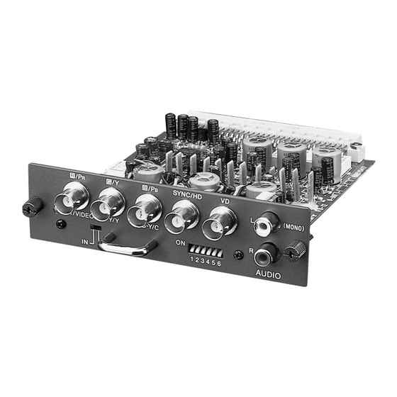
2-3. INPUT MODE ..................2-1(E) 2-4. OUTPUT MODE ..................2-2(E) SEMICONDUCTORS EXPLODED VIEWS 4-1. MAIN UNIT (IFB-12 (OLD)) ............... 4-1 4-2. MAIN UNIT (IFB-12 (NEW), IFB-12A) ............. 4-2 ELECTRICAL PARTS LIST BLOCK DIAGRAMS DIAGRAMS 7-1. SCHEMATIC DIAGRAMS AND PRINTED WIRING BOARDS ....7-1 SCHEMATIC DIAGRAMS •... - Page 6 English The IFB-12A signal interface board is a PC board to be mounted on WARNING the projector or the signal interface switcher, etc. so that RGB and audio signals from a computer, etc. can be input or output to a signal For the customers in the USA interface switcher.
- Page 7 5 DIP switch Rotary switch Set the position of the DIP switch according to the input signal. (Refer to “Setting the DIP switch”.) Never change the Mounting the IFB-12A setting of the JP5 connector. Note Mounting or removal of signal interface boards must be performed by qualified personnel only.
- Page 8 Setting the DIP Switch Specifications Input connectors Set the DIP switch to the appropriate position according to the input /VIDEO connector (BNC type): Red signal input, 0.7 Vp-p ± 2 dB, R/R-Y/P signal. 75 ohms terminated Component R-Y signal input, 0.7 Vp-p ± 2 dB, 75 ohms terminated Input mode can be selected signal input, ±0.35 Vp-p ±...
-
Page 9: Circuit Description
When the IN/OUT switch (S2: IFB-12 (OLD)), (SW2: OUT select switch is used to select the power for the input IFB-12 (NEW), IFB-12A) is set to the IN side and SEL or output circuit. (C19) terminal becomes LOW, this mode is set. -
Page 10: Output Mode
Video signals input from the BNC terminal are passed HIGH, this mode is set. IN/OUT terminal of CN3 (B23) through relays RY1, 2, and 3 (IFB-12 (OLD)), RL1, 2, and (IFB-12 (OLD)), J1 (B23) (IFB-12 (NEW), IFB-12A) 3 (IFB-12 (NEW), IFB-12A) and are input to +6 dB becomes LOW and informs the outside of the output mode. -
Page 11: Semiconductors
SECTION 3 SEMICONDUCTORS GS4881-CKA HN1A01F NJM082BM HN1B01F NJM2903M HN1C01F OPA658U SN75157PS SN75453BPS RN1310 TOP VIEW RN1423 8pin SOP 2SA1162-G 2SA812 MPC100A 2SC1623 SN74HC02ANS TC74HC02AF TOP VIEW 14pin SOP 2SA1388 NJM78L05A DCC010 1SS226 TA7810S RD2.7SB TC4W66F ANODE CATHODE 5pin CHIP IFB-12/12A... -
Page 13: Exploded Views
: 7-684-023-04 NUT (M3) : 7-623-208-22 WASHER (3.0) : 7-622-207-05 NUT (M2.6) supplied with Rf.No. Part No. Description Remark 4-032-851-01 HANDLE 4-055-636-01 SCREW 9-939-566-01 CONNECTOR, BNC 9-939-575-01 PANEL (IFB-12 BOARD) * 9-939-836-01 AUDIO SUB BOARD COMPLETE * 9-939-574-01 IFB-12 BOARD, COMPLETE IFB-12/12A... - Page 14 : 7-622-207-05 NUT (M2.6) IFB-12 IFB-12A supplied with Rf.No. Part No. Description Remark 4-032-851-01 HANDLE 4-055-636-01 SCREW 9-939-566-01 CONNECTOR, BNC 9-939-575-01 PANEL (IFB-12 BOARD) * 9-939-836-01 AUDIO SUB BOARD COMPLETE * 9-939-574-02 IFB-12 BOARD, COMPLETE * 9-939-574-03 IFB-12A BOARD, COMPLETE IFB-12/12A...
-
Page 15: Electrical Parts List
U/C, AEP: S/N 041,751 and later Rf.NO. PART NO. DESCRIPTION REMARK Rf.NO. PART NO. DESCRIPTION REMARK * 9-939-574-01 IFB-12 (OLD) BOARD, COMPLETE 1-126-967-11 ELECT 47uF ****************************************** 1-124-779-00 ELECT 10uF < CAPACITOR > 1-164-004-11 CERAMIC CHIP 0.1uF 1-164-004-11 CERAMIC CHIP 0.1uF... - Page 16 IFB-12 ( OLD ) Rf.NO. PART NO. DESCRIPTION REMARK Rf.NO. PART NO. DESCRIPTION REMARK 1-164-004-11 CERAMIC CHIP 0.1uF 8-719-800-76 DIODE 1SS226 1-126-967-11 ELECT 47uF 8-719-800-76 DIODE 1SS226 1-124-779-00 ELECT 10uF 8-719-800-76 DIODE 1SS226 1-164-004-11 CERAMIC CHIP 0.1uF 1-164-004-11 CERAMIC CHIP 0.1uF...
- Page 17 IFB-12 ( OLD ) Rf.NO. PART NO. DESCRIPTION REMARK Rf.NO. PART NO. DESCRIPTION REMARK 9-939-536-01 TRANSISTOR RN1423 1-216-121-11 METAL, CHIP 1/10W 9-939-536-01 TRANSISTOR RN1423 1-216-049-91 METAL, CHIP 1/10W 9-939-535-01 TRANSISTOR RN1310 9-939-535-01 TRANSISTOR RN1310 1-216-049-91 METAL, CHIP 1/10W 9-939-537-01 TRANSISTOR HN1B01F...
- Page 18 IFB-12 ( OLD ) Rf.NO. PART NO. DESCRIPTION REMARK Rf.NO. PART NO. DESCRIPTION REMARK R109 1-216-001-00 METAL, CHIP 1/10W R178 1-216-047-91 METAL, CHIP 1/10W R110 1-216-001-00 METAL, CHIP 1/10W R179 1-216-047-91 METAL, CHIP 1/10W R111 1-216-001-00 METAL, CHIP 1/10W R181...
- Page 19 IFB-12 ( NEW ) /IFB-12A Rf.NO. PART NO. DESCRIPTION REMARK Rf.NO. PART NO. DESCRIPTION REMARK * 9-939-574-02 IFB-12 (NEW) BOARD, COMPLETE 1-164-004-11 CERAMIC CHIP 0.1uF ******************************************* 1-163-217-11 CERAMIC CHIP 1PF 0.25PF 50V * 9-939-574-03 IFB-12A BOARD, COMPLETE 1-163-084-00 CERAMIC CHIP 1.5PF 0.25PF 50V ************************************ 1-163-084-00 CERAMIC CHIP 1.5PF...
- Page 20 IFB-12 ( NEW ) /IFB-12A Rf.NO. PART NO. DESCRIPTION REMARK Rf.NO. PART NO. DESCRIPTION REMARK 9-939-566-01 CONNECTOR, BNC (SYNC HD) < JACK > 9-939-566-01 CONNECTOR, BNC (VD) 9-939-564-01 CONNECTOR (DIN) (96P) 1-564-515-11 CONNECTOR (12P) < CIRCUIT MODULE > 1-564-508-11 CONNECTOR (5P)
- Page 21 IFB-12 ( NEW ) /IFB-12A Rf.NO. PART NO. DESCRIPTION REMARK Rf.NO. PART NO. DESCRIPTION REMARK 9-881-616-01 METAL, CHIP 1/2W 1-216-683-11 METAL, CHIP 0.50% 1/10W 1-216-675-11 METAL, CHIP 0.50% 1/10W 1-216-049-91 METAL, CHIP 1/10W (IFB-12A) 1-216-659-11 METAL, CHIP 2.2K 0.50% 1/10W...
- Page 22 IFB-12 ( NEW ) /IFB-12A Rf.NO. PART NO. DESCRIPTION REMARK Rf.NO. PART NO. DESCRIPTION REMARK 1-216-021-00 METAL, CHIP 1/10W R141 1-216-022-00 METAL, CHIP 1/10W R100 1-216-308-00 METAL, CHIP 1/10W R142 1-216-030-00 METAL, CHIP 1/10W R101 1-216-022-00 METAL, CHIP 1/10W R143...
- Page 23 IFB-12 ( NEW ) /IFB-12A AUDIO SUB Rf.NO. PART NO. DESCRIPTION REMARK Rf.NO. PART NO. DESCRIPTION REMARK R204 1-216-675-11 METAL, CHIP 0.50% 1/10W * 9-939-836-01 AUDIO SUB BOARD, COMPLETE R205 1-216-049-91 METAL, CHIP 1/10W ***************************************** R206 1-216-065-91 METAL, CHIP 4.7K...
-
Page 25: Block Diagrams
IFB-12 (OLD) IFB-12 (OLD) SECTION 6 BLOCK DIAGRAM IC19 R/C/R-Y R/C/R-Y R/C/R-Y HD/CS HD/CS HD/CS R/PR +10V +10V R IN/OUT R-Y/VIDEO IC20 G/Y/Y G/Y/Y (POWER) G/Y/Y G IN/OUT IC21 B/C/B-Y B/C/B-Y B/C/B-Y SYNC B/PB VIDEO B IN/OUT B-Y/C SYNC SEP... - Page 26 IFB-12 (NEW) /IFB-12A IFB-12 (NEW) /IFB-12A IC19 R/C/R-Y R/C/R-Y R/C/R-Y IC20 HD/CS HD/CS HD/CS R/PR +10V +10V R IN/OUT IC21 R-Y/VIDEO G/Y/Y G/Y/Y (POWER) G/Y/Y G IN/OUT RELAY DRIVE B/C/B-Y B/C/B-Y B/C/B-Y H-THRU B/PB B IN/OUT V-THRU B-Y/C SW10 IFB-12A...
-
Page 27: Diagrams
SECTION 7 DIAGRAMS 7-1. SCHEMATIC DIAGRAMS AND PRINTED WIRING BOARDS J: S/N030,001 to 031,450 IFB-12 (OLD): U/C, AEP: S/N 040,001 to 041,750 J: S/N 031,451 and later FB-12 (NEW): U/C, AEP: S/N 041,751 and later Note: • All capacitors are in µF unless otherwise noted. pF: µµF 50 WV or less are not indicated except for electrolytics. - Page 28 IFB-12 (OLD) (2/3) BOARD IC2 GS4881-CKA COMPOSITE SUPPLY SYNC VOLTAGE – VIDEO ODD/EVEN INPUT FIELD INDEX – VERTICAL SYNC CAPACITOR CHARGE CURRENT DEFAULT BURST GATE/ BACK PORCH CLAMP – – – – IFB-12 (OLD) (2/3) BOARD IFB-12 (OLD) (2/3) BOARD...
- Page 29 WAVEFORMS 0.7 Vp-p (H) 0.7 Vp-p (H) 0.7 Vp-p (H) 4.5 Vp-p (H) 4.5 Vp-p (V) • IFB-12 (OLD) (2/3) BOARD WAVEFORMS 4.1 Vp-p (H) 4.1 Vp-p (V) 4.0 Vp-p (V) 4.5 Vp-p (H) • IFB-12 (OLD) (3/3) BOARD WAVEFORMS 2.0 Vp-p (H)
- Page 31 IFB-12 (OLD) IFB-12 (OLD) IFB-12 (OLD) BOARD *: B SIDE < DIODE > < LED > *E-2 *E-1 *E-2 < TRANSISTOR > *C-1 *D-2 *D-2 *D-3 *D-4 *D-5 *C-1 *E-3 *C-2 *E-4 *E-5 *C-2 *A-4 *C-2 < IC > *C-1...
- Page 32 IFB-12 (OLD) (1/3) IFB-12 (OLD) (1/3) R/G/B +5V IN :CHIP RGB/VIDEO 5V-2 +5V IN 5V-2 RD2.7SB RN1310 MODE SW RN1423 MODE SW CODE1 RN1423 MODE SW TO IFB-12(3/3) VIDEO/YC RN1423 DCC010 MODE SW MODE SW R/G/B RN1423 MODE SW DCC010...
- Page 33 IFB-12 (OLD) (2/3) IFB-12 (OLD) (2/3) TO IFB-12(1/3) +10V IN +10V IN +5V IN 10V-2 GS4881-CKA 10V-2 5V-2 SYNC SEP. 10 16V :TA-CP B:CHIP R219 :CHIP 2.2k 100k :CHIP :CHIP RN:CHIP :CHIP V IN DD/EVN 33k :CHIP REST +10V IN...
- Page 34 IFB-12 (OLD) (3/3) IFB-12 (OLD) (3/3) AUDIO L/R TO IFB-12(2/3) AUDIO AUD.L AUD.L AUDIO L R/G/B PROTECT +10V OUT 10V-3 IC10 MPC100AU 10 16V (5.0) PEAKING SW OPA658U :CHIP RC3000 :CHIP DCCO10 :CHIP :RN-CP 100k PROT 1 2 3 4 5 6 7 8...
-
Page 35: Ifb-12 (New), Ifb-12A (1/3) Board
5.0 Vp-p (V) CAPACITOR CHARGE CURRENT DEFAULT BURST GATE/ BACK PORCH CLAMP – • IFB-12 (NEW) /IFB-12A (2/3) BOARD WAVEFORMS – – – 4.7 Vp-p (H) 4.1 Vp-p (H) 4.4 Vp-p (V) 4.0 Vp-p (V) IFB-12 (NEW) /IFB-12A (2/3) BOARD IFB-12 (NEW) /IFB-12 (3/3) BOARD 1.7 Vp-p (H) - Page 36 IFB-12 (NEW) IFB-12 (NEW) IFB-12 (NEW) BOARD *: B SIDE < DIODE > < LED > *E-2 *E-1 *E-2 < TRANSISTOR > *C-1 *D-2 *D-1 *D-2 *D-3 *D-4 *D-5 *D-1 *E-3 *D-1 *E-4 *E-5 *D-2 *A-4 *C-2 *D-2 *D-1 *B-3...
- Page 37 IFB-12A IFB-12A IFB-12 BOARD *: B SIDE < DIODE > < LED > *E-2 *E-1 < TRANSISTOR > *C-3 *C-1 *D-1 *D-2 *C-2 *D-3 *D-4 *C-3 *D-5 *E-3 *C-2 *E-4 *D-1 *E-5 *A-4 *D-2 *D-2 *C-2 *D-2 *D-1 *B-3 *C-1...
- Page 38 IFB-12 (NEW) /IFB-12A (1/3) IFB-12 (NEW) /IFB-12A (1/3) R/G/B +5V IN 5V-2 RGB/VIDEO :RN-CP *marked parts SSH-06 RN1310 HZM2.7NB3 Ref.No. IFB-12(NEW) IFB-12A MODE SW R133 4.7k R133 R134 4.7k R215 4.7k :RN-CP R216 4.7k R217 4.7k 2SC1623 MODE SW R124...
-
Page 39: Ifb-12A Board
IFB-12 (NEW) /IFB-12A (2/3) IFB-12 (NEW) /IFB-12A (2/3) AUDIO L/R TO IFB-12A(1/3) IFB-12(NEW) *marked parts Ref.No. IFB-12(NEW) IFB-12A AUDIO L/R 2.2k 1.5k 3.3k V-THRU THRU A-12W-K SW10 H-THRU SSJ-022M 2SA812 :RN-CP SLICER CONV :AL-CP IFB-12A +12V 2SC1623 +10V IN DCC010 4.7k... - Page 40 IFB-12 (NEW) /IFB-12A (3/3) IFB-12 (NEW) /IFB-12A (3/3) AUDIO L/R AUDIO L TO IFB-12A(2/3) AUDIO AL-OUT R/G/B AL-OUT AL-OUT PROTECT 220k :RN-CP :RN-CP +10V OUT AR-OUT 10V-3 IC10 +10V :TA-CP MPC100AU 220k :RN-CP :RN-CP OPA658U (5.0) PEAKING SW :RN-CP 10 16V :TA-CP...
- Page 41 The material contained in this manual consists of information that is the property of Sony Corporation and is intended solely for use by the purchasers of the equip- ment described in this manual. Sony Corporation expressly prohibits the duplication of...
- Page 42 English/Japanese 98KY05133-1 Sony Corporation Printed in Japan Broadcasting & Professional Systems Company 9-922-633-02 © 1998. 11...
Need help?
Do you have a question about the IFB-12 and is the answer not in the manual?
Questions and answers