Table of Contents
Advertisement
Advertisement
Table of Contents

Related Manuals for PERSEE T6 U


Summary of Contents for PERSEE T6 U
- Page 1 T6 U Spectrophotometer INSTRUCTION MANUAL PERSEE ANALYTICS, INC.
- Page 2 Introduction Thanks for your purchase of the PERSEE ANALYTICS, INC. T6U spectrophotometer. UV-Visible Spectrophotometer is a well-accepted, documented technique with many applications. The technique is extensively used for the analysis of agricultural products and is widely used in public health, environmental protection, life sciences industries and many other organic and biochemical applications.
- Page 3 Icons Please pay attention to the following icons appearing in the book. Direction guide: direction guide when you mount and dismount the instrument. Caution: Improper operation may cause unnecessary damage or accidents. Eyes protection: Please wear glasses for the inner ultraviolet radiation and strong light. Scald: Don’t touch to avoid scalding.
-
Page 4: Table Of Contents
Contents CHAPTER 1 INSTALLATION ........................1 1.1 Packing List ........................1 1.2 Environmental Requirements ................2 1.3 check the mains voltage ..................3 1.4 Instrument Installation ....................4 CHAPTER 2 INSTRUMENT CONSTRUCTION ..................6 2.1 Front view ..........................6 2.2 Side view .......................... - Page 5 PERSEE ANALYTICS, INC. Information in this publication is subject to change without notice, as PERSEE ANALYTICS, INC. continues to develop the latest technologies and products for our customers.
-
Page 6: Chapter 1 Installation
Chapter 1 Installation 1.1 Packing List T6U main unit and the necessary accessories are packed in the packing box. We also provide optional accessories at your discretion. Upon receiving your instrument, please check that all the items listed below are present: Name Q’ty T6U main unit... -
Page 7: Environmental Requirements
1.2 Environmental Requirements To insure correct operation and stable performance over an extended period of time, install the T6U in a location that meets the following conditions: 1. Operation conditions: Condition Altitude Temp (º C) Humidity (%RH) Non-condensing Non-operating 0-2000m 5-45 20-80 (Transport) -
Page 8: Check The Mains Voltage
1.3 check the mains voltage Verify the mains voltage before turning on the power, or it may damage the instrument. T6U is designed to operate on 230V, 120VA and 50/60Hz mains supply. Confirm the AC main is earthed in the building before turning on the instrument. Turn off the power and cover the instrument after use. -
Page 9: Instrument Installation
1.4 Instrument Installation The following procedures will help you finish the installation. Step one: Unpack the instrument and place it on the stable workbench. Unpack the instrument carefully and set it down gently! The workbench should be stable and free from vibration. Step two: Connect to the printer Be sure to turn off the power of the instrument and the printer before connecting via the parallel port, otherwise it may damage the devices. - Page 10 Step five: When the initialization procedure is completed, the main menu will automatically appear on the screen.
-
Page 11: Chapter 2 Instrument Construction
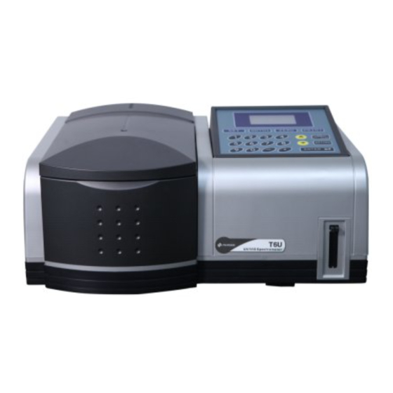
Chapter 2 Instrument construction 2.1 Front view 2.2 Side view... -
Page 12: Rear View
2.3 Rear view 2.4 keypad description Numeric keys Input the numeric values Function keys Set the working mode Set the wavelength Zero Abs (100%T) Print data Edit keys Start measurement Used to quit operation and Page keys return Used to confirm the current Page up parameters and operating mode Page down... -
Page 13: Chapter 3 Operation
Chapter 3 Operation 3.1 Introduction The main menu (Fig.3-1) Press 【▲】 and 【▼】 to move the cursor to the required function, then press【ENTER】to gain access to the screen of selected option; Press 【RETURN】 to return to the preceding page. There are three options available on the main menu: ⊙... -
Page 14: Photometric Measurement
3.2 Photometric Measurement This mode allows the user to measure the Abs or transmittance at a fixed wavelength, and perform measurement by using K factor; you also can print out the measurement result. Main menu of photometric measurement Press【▲】 and 【▼】 to select “Photo”, then press【ENTER】to gain access to the main menu of photometric measurement. - Page 15 (Fig.3-5) At the bottom of this page, enter the gain value by pressing the numeric keys (1~8). The range is 1~8. If the entered figure exceeds the range, the system will delete what has been entered automatically and you should start a new entry again. Press 【ENTER】to confirm, and press 【RETURN】to quit, returning to the menu of parameters setting.
- Page 16 (Fig.3-7) (Fig.3-8) Press 【▲】 and 【▼】 to move the cursor to the required option, then press【ENTER】 to gain access to the menu. Press 【RETURN】 to quit, returning to the preceding menu. ⊙ Setting Module Style Press 【▲】 and 【▼】 to move the cursor to the required option, then press【ENTER】 to select among “8 cell”, “5 cell”...
- Page 17 blank value. If you select yes for the cell blank, the test is necessary. Put blank samples in each cell before test, the system will record the measurement values of each cell automatically. If you select “yes” for both reagent blank and cell blank, you can perform cell blank for each cell and take the sample in No.1 cell as the blank to correct the measured values of other cells.
- Page 18 Setting the working wavelength In the case of photometric measurement (Fig.3-1), press【GOTOλ】 to set wavelength, as shown in Fig.3-9. (Fig. 3-9) At the bottom of this page, enter the wavelength by pressing the numeric keys (0~9) and decimal point 【....
- Page 19 On the menu of Fig.3-10, press 【PRINT】 to print the data in the data area. The system will clear the data area after printout. When the data area is full or the user changes the setting of the system, it will ask the user whether to print the measured data when the user starting measurement the next time.
-
Page 20: Card Program
3.3 Card Program The MCU mode only allows the user to perform photometric measurement. If you want to perform other measurements, please insert the required program card into the instrument. We provide multiple program cards for your option, as well as other cell holders and software etc. Please refer to the optional accessories for the detailed information of accessories. -
Page 21: System Set
3.4 System Set This mode allows the user to set the working parameters, such as tungsten lamp On/Off, deuterium lamp On/Off, work mode, time set, wavelength correction, and dark current correction. In the case of main menu of the instrument, press 【▲】 and 【▼】to move the cursor to the option of system set. - Page 22 perform. Press 【RETURN】 to quit PC mode. (Fig. 3-15) The software is an optional accessory. It provides you more powerful analysis function. Please contact your local dealer for more detailed information. ⊙ Time Set In the case of system set, press【▲】 and 【▼】 to move the cursor to the Time Set, then press 【ENTER】, as shown in Fig.3-16: (Fig.
- Page 23 (Fig. 3-17) ⊙ Printer Selection In the case of system set, press 【▲】 and 【▼】 to move the cursor to the option of Printer, then press 【ENTER】 to set. There are two modes, uP and HP. Each time you press 【ENTER】, the uP and HP will change alternately.
- Page 24 In the case of system set, press 【▲】 and 【▼】 to move the cursor to the option of Reset System, then press 【ENTER】 to gain access to the menu of reset system. (Fig. 3-20) In the case of reset system, press 【▲】 and 【▼】 to move the cursor to the required option, then press 【ENTER】.
- Page 25 ⊙ About In the case of system set, press 【▲】 and 【▼】 to move the cursor to the option of About, then press 【ENTER】. (Fig. 3-22) Press 【RETURN】 to return to the menu of system set.
-
Page 26: Chapter 4 Specifications
Chapter 4 Specifications Wavelength 190nm-1100nm Range Wavelength +1.0nm (with automatic wavelength correction) Accuracy ≤0.2nm Wavelength Reproducibility Spectral 2 nm Bandwidth Photometric +0.3 %T Accuracy Photometric ≤0.15 %T Reproducibility ≤0.05 %T(220nm NaI,340nm NaNo2) Stray Light 0.002A(1000-200nm,after 1 hour warm-up) Baseline Flatness Noise 0%T:+0.05%T (500nm) -
Page 27: Chapter 5 Optional Accessories
Chapter 5 Optional accessories UVWIN 5.0 software UVWIN 5.0 software is used in the UV-VIS spectrophotometer. The powerful and user-friendly software can greatly improve your work efficiency. The functions: Photometric measurement Quantitative measurement Spectrum scanning Kinetics measurement 3D presentation The software allows the user analyzes and shares the data. And the dedicated software packages can satisfy the needs of various industries. -
Page 28: Chapter 6 Maintenance
Chapter 6 Maintenance 6.1 Daily Care Check the sample compartment Check if there is spilled liquid on the floor of the sample compartment before and after use. Wipe off any spilled liquid immediately to prevent evaporation and corrosion of the compartment, which may cause erroneous result. -
Page 29: Maintenance
6.2 Maintenance 1. The screen fails to display or doesn’t display clearly after power on Check the contrast dial--use the plain screwdriver to adjust the “CONTRAST” dial rear of the instrument. 2. The instrument does not operate at all; noting appears on LCD screen. Check the mains voltage according to the page five “check the mains voltage”. - Page 30 Set the change lamp wavelength, the instrument will switch over the lamp automatically. Why isn’t the stray light eligible? The poor power and the resultant raise of the dark current adversely affect it. Perform dark current correction will solve the problem. In addition, if the instrument is placed in the humid environment for a long time, it will also cause the stray light raises higher.
- Page 31 Appendix 1 Be sure to turn off the power when replace the lamps. Otherwise, it is dangerous. Light source replacement Please follow the following procedures to replace the tungsten lamp and deuterium lamp: Step one: turn the knob at the right lower bottom counterclockwise to make it vertical to the cover,as shown in Fig.
- Page 32 Fig. 7-4 Step five: replace the required light source 1) Tungsten lamp replacement Turn the W lamp flake right slightly. Remove the old tungsten lamp by wearing a pair of cotton gloves. Insert a new tungsten lamp into the base(12V20W), turn the flake to its original position. 2)...
- Page 33 Appendix 2 Clean the dust filter Switch off the power of the instrument, and place the instrument as shown in Fig. 7-5. Take off the filters and clean them. Fig.7-5...
Need help?
Do you have a question about the T6 U and is the answer not in the manual?
Questions and answers