
Related Manuals for Enovation Controls Murphy EMS PRO LITE


Summary of Contents for Enovation Controls Murphy EMS PRO LITE
- Page 1 EMS PRO LITE Engine Monitoring System Controller Installation and Operations Manual 2015-03-23 00-02-0787 Section 40...
- Page 2 In order to consistently bring you the highest quality, full-featured products, we reserve the right to change our specifications and designs at any time. Enovation Controls has made efforts to ensure the reliability of the EMS PRO LITE and to recommend...
- Page 3 • Please contact Enovation Controls immediately if you have any questions. IMPORTANT! Improper use and operation of electronic products can be dangerous. It is required that point-of- operation guarding devices be installed and maintained.
-
Page 5: Table Of Contents
CONTENTS Introduction ................... 1 User Interface and Navigation ........... 1 Membrane Keypad ............1 Key Switch............... 2 Stop Switch ..............3 Screens Displayed ............3 Quick Set Up ................7 Setting the Date/Time Clock ............7 EMS PRO LITE on electronically-governed Engine ....8 EMS PRO LITE on mechanically-governed Engine .... - Page 6 Menus ..................22 S-Number Description and Listing ........ 22 P-Number Description and Listing ........ 33 M-Number Description and Listing ........ 35 Inputs and Outputs ..............38 Digital Inputs ..............38 Analog Inputs ..............39 Digital Outputs ............... 40 PCBA Shunts ..............41 General Information ..............
- Page 7 P-NUMBERS ..............48 S-NUMBERS ..............48 M-Numbers..............48 Loading a Program ..............48 Installation .................. 49 EMS PRO LITE Dimensions ............ 49 EMS PRO LITE Wiring Diagram..........50 Specifications ................51...
- Page 8 NOTES...
-
Page 9: Introduction
Introduction The EMS PRO LITE is a customizable pump-controller designed with dewatering and irrigation applications in mind. EMS PRO LITE offers field-adjustable operating parameters without the need for a laptop computer. It can support both mechanical and J1939 electronic engines. This unit offers selectable auto start/stop with auto-throttling options: Floats, and Transducer. -
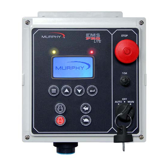
Page 10: Key Switch
Description ICON START = In the “MAN” (manual) mode this initiates a start sequence. STOP = In the “MAN” (manual) mode this initiates a stop sequence. THROTTLE INCREASE = In the “MAN” (manual) mode this increases engine speed. THROTTLE DECREASE = In the “MAN” (manual) mode this decreases engine speed. -
Page 11: Stop Switch
/ Enovation Controls screen scroll you are, when you press the down arrow, the top line of the text page could be either FW MURPHY, MURPHY, or ENOVATION CONTROLS. BUILD XXXXX The current BUILD is usually a 5-digit number. Make note of the build number. - Page 12 Screens Displayed Screen Name Description LEAD SPD XXXX If the controller is in AUTO mode, the internally generated lead/command speed is displayed in RPM. If the controller is in MANUAL, this does not display. SELECTOR XXXX This displays the position of the key: AUTO, or MAN. When a start signal is active, the display may include the following state or start options in place of the Auto or Manual states.
- Page 13 Screens Displayed Screen Name Description • ST: (STATE XXXX), CRANK OFF occurs when cycle cranking begins. continued During this state, the crank output is turned OFF. • RECRANK DELAY occurs if the engine speed drops below the “crank stop” set point before the “shutdown lockout delay”...
- Page 14 Screens Displayed Screen Name Description LEVEL XX.X This displays the current system level as sensed from a (IF SELECTED) transducer. LOCAL THROT This is only show if Local Throttle is selected in S-34. (IF SELECTED) SOOT LEVEL This shows the soot level percentage from SPN 3719. (IF SELECTED) There are also 3 alarms associated with this Status sent from the ECU.
-
Page 15: Quick Set Up
Quick Set Up This section gives information on setting up specific functions within the controller such as time, date, engine type, Tier 4 activity, and Unit display type (Metric or US Standard). Other menus, such as the S-menu, P- menu, and M-menu must also be setup before placing the unit in service. NOTE: This section is a reference guide. -
Page 16: Ems Pro Lite On Electronically-Governed Engine
EMS PRO LITE on electronically-governed Engine The EMS PRO LITE factory defaults are set to run on an electronically governed engine. See the following section to use the controller on a mechanically governed engine. EMS PRO LITE on mechanically-governed Engine To use the controller on a mechanically governed engine, follow the steps below: 1. -
Page 17: Pressure Start/Stop Type
Pressure Start/Stop Type The Pressure Start/Stop Type allows you to automatically start and stop the engine using a pressure transducer to measure low and high set points. Follow the steps below to set this start/stop feature. 1. Access the S Menu by pressing [Menu]. 2. -
Page 18: 2-Float Start/Stop Type
7. Review and modify the settings for S57 through S71 for Level Start/Stop Type. To modify a setting, press [Enter] when the setting is highlighted. When finished with the modification press [Enter] again. Refer to the S-Number table in Menus for a description of the S- Numbers settings. -
Page 19: Throttle To Level
S-numbers are associated with emission control actions: S73 (Tier Rating), S74 (Tier State), and S75 (Request DPF Regen) and can be seen in the S-number table on page 22. NOTICE: Enovation Controls does not control the Emissions ECU, please consult with your engine manufacturer for specific emissions operation. - Page 20 If you are using the EMS PRO LITE on an Interim Tier 4 engine, please read and understand the information for the following S-numbers: S73, S74, and S75 in the S-number table, page 22. Also, read and understand the following information and steps to set up Tier 4 Emission options. The controller displays the SOOT level on the display when the engine has been de-rated and/or when regeneration (regen) is required to return to normal service.
-
Page 21: Unit System - Metric Or English
NOTE: Once the regen has started, allow this menu to display until the regen is complete and NO is displayed on the menu. 5. Press [Menu] to exit the S Menu. Unit System – Metric or English This setting allows you to change the default units from English units °... - Page 22 THIS PAGE INTENTIONALLY LEFT BLANK Section 40 00-02-0787 ~ 14 ~ 2015-03-23...
-
Page 23: Operating Instructions
Operating Instructions AUTO Start/Stop Sequence The following choices are available in the “Start/Stop type” S-Numbers: • Floats (2 contacts): Both contacts close for start and both contacts re-open for stop. • Transducer: Starting and stopping is controlled by S- Number set points. System pressure and level are available in the “transducer type”... - Page 24 The start condition must remain active throughout the start delay, or the delay will reset to zero. • When the “START DELAY” expires, the following will occur: The STATE: text line will display “PRESTART DELAY”. The “prestart delay” begins timing. ...
- Page 25 NOTE: OVERCRANK If the engine fails to start after the number of cranking attempts is exceeded, OVERCRANK will be indicated on the display. The auto start sequence will be stopped, requiring manual reset of the controller. The controller is reset by moving the panel key switch to the "OFF"...
-
Page 26: Stop Sequence
NOTE: If Electronic is selected for Engine Type, the ECU will control and arm engine shutdowns. The exceptions are any shutdowns external to the ECU, in which case the controller will arm engine shutdowns. • When the “warm-up delay” expires, the following will occur: ... -
Page 27: Manual Start/Stop Sequence
Manual Start/Stop Sequence There is only one start option in Manual Mode. Start Sequence • When you place the AUTO-OFF-MAN key switch in the MAN position (with no failures present) the SELECTOR text line will display MAN. The STATE text line will display PANEL READY. •... -
Page 28: Stop Sequence
• If the Fuel/ECU Enable output is not already ON, t he Fuel/ECU Enable will be turned ON. NOTES: WAIT FOR ECU. If ECU is selected in engine type, the controller will go through a fixed 10-second delay to allow the ECU to warm up prior to cranking. -
Page 29: Special Features
• When the “cooldown delay” expires, the following will occur: The SELECTOR text line will display “AUTO” and the STATE text line will display “PANEL READY”. The fuel/ECU enable is turned OFF. The Alt excite output is turned OFF. ... -
Page 30: Menus
Menus The EMS PRO LITE has S-number, P-number, and M-number menus. This section contains a table for each number type that lists available numbers and a description of the function of each number. See the Entry Code Supplement for information on accessing the number menus. - Page 31 Description OVERSPEED: This setting allows you to enter the highest speed the engine can run before damage is caused. If the controller senses that the engine has exceeded this speed, it will signal the engine to shutdown. Factory set to 2000. LOCKOUT DELAY: This delay is used to ignore conditions such as low oil pressure when the engine first starts to allow the pressure time to reach its normal operating range (adjustable from 1 to 60 seconds).
- Page 32 Description LOP HI SPEED: Set this to your engine maximum speed. If the engine is running at this speed, and the oil pressure reaches the set point selected in S11, the controller will initiate an automatic shutdown. Factory set to 1600. The Graph above shows how the set point changes between your high-speed set point and low-speed set point.
- Page 33 Description COOLDOWN DLY: You can adjust this variable to the number of seconds you wish to cool down your engine before it shuts OFF after a stop signal is received (adjustable from 1 to 9,999 seconds). Factory set to 180. CRANK TIME: Set this delay to the desired amount of time you want each engine-cranking attempt to last.
- Page 34 Description MAX ENG RPM: When throttling in the AT LOAD state, the engine will not throttle above this set point. Factory set to 1600. RATE INC RPM: This set point is used to customize how fast or slow the controller will increase the engine RPM while throttling. Experiment with this number until the proper throttling is achieved.
- Page 35 Description SET ADJ DLY: This delay allows the controller to stop adjusting the engine RPM for this delay. It allows for a settling time after making a speed adjustment (adjustable from 1 to 9,999 seconds). (All engines) Factory set to 1. STRT/STP SEL: Enter the type of auto start/stop required: FLOATS or TRANSDUCER.
- Page 36 Description SENDER TYPES: (S41 is only visible if S38=Mechanical.) This set point allows you to select between Murphy-resistive sending units or VDO-resistive sending units for Pressure and Temperature senders. Factory set to MURPHY. START DLY: Set this delay on engine start to the number of seconds that the start signal must be present before the controller accepts it and initiates an auto start sequence (adjustable from 1 to 9,999 seconds).
- Page 37 Description HI DISCH PSI: (S45 is only visible if S35 = Transducer & S37 = Pressure.) When “pressure” is selected in either the start / stop or throttle type, an immediate shutdown will occur if the pressure rises to this set point. (adjustable from 0 to 1000 PSI) Factory set to 90. Entering “0”...
- Page 38 Description PSI XDUCER MIN CNT: (S45 is only visible if S35 = Transducer & S37 = Pressure.) With 1 VDC or 4mA applied to the analog channel, make the top line read the same value as the bottom line. Factory set to 181.
- Page 39 Description LEVEL TYPE: (S62 is only visible if S35 = Transducer and S37 = Level.) Enter type of level control required. The choices are “Empty”, “Fill”, or “Proportional”. Empty starts on high and stops on low. Fill starts on low and stops on high. S57 and S58 should be set accordingly.
- Page 40 Description LVL CNT MIN: (S68 is only visible if S35 = Transducer and S37 = Level.) With 1 VDC or 4mA applied to the analog channel, make the top line read the same value as the bottom line. Factory set to 181. (If transducer is 0-5 VDC, enter 0 in this set point) LVL XDCR OOR HI: (S69 is only visible if S35 = Transducer and S37 = Level.) When “level”...
-
Page 41: P-Number Description And Listing
Description REQUEST DPF REGEN: This option is only available if: S73 (Tier Rating) is set to Tier 4 S38 (Engine Type) is set to ECU Engine RPM is above S23 (Crank Stop RPM) ECU output (Output 1) is ON. Selecting YES initiates a regen. After pushing YES, the display will go from NO to YES when the regen is complete. - Page 42 Name Description Number WED SEL Set this to YES if you want to start your engine on WEDNESDAY. Set it to NO if you want to lock out the start time on this day. Factory set to NO. THR SEL Set this to YES if you want to start your engine on THURSDAY.
-
Page 43: M-Number Description And Listing
Name Description Number CLK C RUN TM This set-point lets you set in the amount of time you would like your engine to run on your first start time. You have three available start times per day (A, B, and C). Factory set to 0.0. - Page 44 Hex View For reading ram locations from 0000H to FFFFH. Factory set to 00H. Force Output Using the down arrow to move the cursor under the correct output. From left to right, outputs are 1-7. Turn on the output using the up arrow button, and off by using the down arrow.
- Page 45 Can 0 Arbitrary This is to allow the can 0 source address to be arbitrary, beginning at whatever is set in M14. Factory set to CAPABLE YES. CAN 0 TERM This is one of the two CAN ports on the Controller. M20 is the other.
-
Page 46: Inputs And Outputs
DSP Contrast Lighten the text to a minimum of 8 or darken the text to a maximum of 35. Factory set to 25. Heater The heater is regulated by the Controller that adjusts the heater depending on the ambient temperature. Turning this to ON could damage the Controller. -
Page 47: Analog Inputs
Analog Inputs Analog Description Sending Unit Type Connector Input Engine Temperature Murphy ES2T or VDO Pin W, 21 Pos. Sender Conn. Set in SENDER TYPES (S39) to Default to Murphy Senders. Engine Oil Pressure (Murphy ES2P or VDO). Pin X, 21 Pos. Sender Conn. -
Page 48: Pcba Shunts
Digital Description Connector Output Fuel/Ignition/ECU Enable (B+) Pin G, 21 Pos. Conn. from R1 relay Reserved Alt Excite (B+) Throttle Decrease (Murphy Throttle Pin R, 21 Pos. Conn Actuator AT-03069) Throttle Increase ((Murphy Throttle Pin S 21 Pos. Conn Actuator AT-03069) Reserved Reserved Prestart (B-) -
Page 49: General Information
These steps may take a few extra minutes to do at the time of installation; but they can save time and expense in the future. Enovation Controls strongly recommends taking these precautionary actions. Diodes Place suppression diodes across all inductive loads. -
Page 50: General Wiring Precautions
LITE Controller live a long and trouble-free operating life. If for any reason a question arises during installation, feel free to call Enovation Controls Technical Support. Fuses There is one 10A fuse installed in the controller. It is on the faceplate and is used for the main power to the panel (Glass SAE type). -
Page 51: Communications
Communications CAN port designated for J1939 communications. RS-485 RS-485 port designated for Modbus RTU (slave) for SCADA. Modbus is available on this port using the Modbus map detailed in the Registers section on the following page. NOTE: Modification to controller is required to use these ports –... -
Page 52: Description
Description The EMS PRO LITE implements a MODBUS RTU style communications protocol. The following describes the communications, and the register and coil implementation for the EMS PRO LITE. Protocol The EMS PRO LITE controller will reply to MODBUS RTU communications. This communications protocol uses RS232 or RS485 standards set to 9600-baud rate, no parity, eight (8) bits and one (1) stop bit. - Page 53 REGISTER TYPE DESCRIPTION 40001 Read Only Running Hours, upper byte. 40002 Read Only Running hours, lower byte. 40003 Read Only Engine RPM 40004 Read Only Battery Voltage. (12.5 will read 125) 40005 Read Only Oil Pressure. 40006 Read Only Engine Temperature. 40007 Read Only System Status: Bits description follows:...
- Page 54 REGISTER TYPE DESCRIPTION 40008 Read Only Shutdown Status: Bits description follows: Bit 0 (LSB) Low Oil Pressure: (1) yes, (0) no. High Engine Temperature: (1) yes, (0) Bit 1 Bit 2 Spare Bit 3 Spare Bit 4 Loss of Speed: (1) yes, (0) no. Bit 5 No Speed Signal: (1) yes, (0) no.
- Page 55 REGISTER TYPE DESCRIPTION 40009, Read only Bit 6 Spare. cont. Bit 7 Spare. Bit 8 Spare. Bit 9 Spare. Bit 10 Spare. Bit 11 Spare. Bit 12 Spare. Bit 13 Spare. Bit 14 Spare. Bit 15 (MSB) Spare. 40010 Read Only Discharge Pressure.
-
Page 56: Entry Code Supplement
The code number is 64. M-Numbers Please call Enovation Controls Technical Support to access this entry code. Loading a Program If a new program is needed, always perform a factory setup after loading into the EMS PRO LITE. -
Page 57: Installation
Installation EMS PRO LITE Dimensions This section contains the EMS PRO LITE dimensions and connection schematics. Mount the EMS PRO LITE in a location that is accessible to the operator. Use connection harnesses to connect to the I/O and the engine. -
Page 58: Ems Pro Lite Wiring Diagram
EMS PRO LITE Wiring Diagram Drawing Notes for the Wiring Diagram (00-02-0814) that is at the center of this manual. In addition, the wiring diagram can be found on the Enovation Controls Web site: http://www.fwmurphy.com/ Section 40 00-02-0787 ~ 50 ~... -
Page 59: Specifications
Specifications Operating Voltage: 8 VDC Minimum to 14.4 VDC Maximum (Designed to work on 12 VDC systems). Operating Temperature: -40 to 80°C (-40 to 176°F) Storage Temperature: -40° to 80°C (-40° to 176°F) Environmental Sealing: IP65 Relative Humidity: 95%RH @ 60°F (140°C) Standby Current: 140mA @ 12VDC for standby current. - Page 60 THIS PAGE INTENTIONALLY LEFT BLANK...
- Page 61 THIS PAGE INTENTIONALLY LEFT BLANK...
- Page 62 THIS PAGE INTENTIONALLY LEFT BLANK...
Need help?
Do you have a question about the Murphy EMS PRO LITE and is the answer not in the manual?
Questions and answers